DMD0527
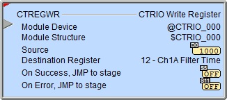
CTREGWR - CTRIO Write Register
The CTRIO Write Register (CTREGWR) instruction is used to write a value from a location in the Do-more controller to the selected internal register of the CTRIO.
The red triangle in the upper left corner indicates the CTRIO Write Register (CTREGWR) is a Fully Asynchronous instruction.
Note: The CTREGWR instruction can be used with both the CTRIO and CTRIO2 modules.

Inputs:
This input is edge-triggered, meaning that each time this input logic transitions from OFF to ON, the CTRIO Write Register (CTREGWR) will:
Write the value to the selected location in the CTRIO module
Run to completion, even if the input logic goes OFF before the operation is complete
Parameters:
Note: Use the F9 key (Element Browser) at any time to see a complete list of the memory locations that are valid in the current field of the instruction.
 Module Device - designates
which CTRIO modules to interact with.
Module Device - designates
which CTRIO modules to interact with.
Part of the configuration for any device is assigning a name to the device. It is that name which will show up in the Module Device selection drop-down menu. For more information on configuring CTRIO devices go to the Module Configuration Section under System Configuration.
Note: no devices available - indicates that there are no CTRIO modules that have been pre-configured to perform this instruction.
Module Structure -
Source - designates the location to store the value read from the CTRIO module. This can be any 32-bit readable numeric location.
Destination Register - selects which of the following internal registers to write:
0 - Ch1Fn1 Accumulator: Channel 1 Function 1 raw count value (e.g. .iReg1 if Ch1Fn1 is unscaled or .iReg2 if Ch1Fn1 is scaled)
1 - Ch1Fn2 Accumulator: Channel 1 Function 2 raw count value (e.g. .iReg1 if Ch1Fn2 is unscaled or .iReg2 if Ch1Fn2 is scaled)
2 - Ch2Fn1 Accumulator: Channel 2 Function 1 raw count value (e.g. .iReg1 if Ch2Fn1 is unscaled or .iReg2 if Ch2Fn1 is scaled)
3 - Ch2Fn2 Accumulator: Channel 2 Function 2 raw count value (e.g. .iReg1 if Ch2Fn2 is unscaled or .iReg2 if Ch2Fn2 is scaled)
4 - Out 0 Position: Output 0's position value.
5 - Out 1 Position: Output 1's position value.
6 - Out 2 Position: Output 2's position value.
7 - Out 3 Position: Output 3's position value.
8 - Ch1Fn1 Reset Value: The value Channel 1 Function 1 accumulator will be set to when the reset bit (e.g. $CTRIO_000_C1F1.Reset) is subsequently set ON, or a subsequent external reset on the CTRIO input is detected (if configured as such).
9 - Ch1Fn2 Reset Value: The value Channel 1 Function 2 accumulator will be set to when the reset bit (e.g. $CTRIO_000_C1F2.Reset) is subsequently set ON, or a subsequent external reset on the CTRIO input is detected (if configured as such).
10 - Ch2Fn1 Reset Value: The value Channel 2 Function 1 accumulator will be set to when the reset bit (e.g. $CTRIO_000_C2F1.Reset) is subsequently set ON, or a subsequent external reset on the CTRIO input is detected (if configured as such).
11 - Ch2Fn2 Reset Value: The value Channel 2 Function 2 accumulator will be set to when the reset bit (e.g. $CTRIO_000_C2F2.Reset) is subsequently set ON, or a subsequent external reset on the CTRIO input is detected (if configured as such).
12 - Ch1A Filter Time (CTRIO2): Software noise filter value in nanoseconds for Channel 1 Input A (for full explanation see here).
13 - Ch1B Filter Time (CTRIO2): Software noise filter value in nanoseconds for Channel 1 Input B (for full explanation see here).
14 - Ch1C Filter Time (CTRIO2): Software noise filter value in nanoseconds for Channel 1 Input C (for full explanation see here).
15 - Ch1D Filter Time (CTRIO2): Software noise filter value in nanoseconds for Channel 1 Input D (for full explanation see here).
16 - Ch2A Filter Time (CTRIO2): Software noise filter value in nanoseconds for Channel 2 Input A (for full explanation see here).
17 - Ch2B Filter Time (CTRIO2): Software noise filter value in nanoseconds for Channel 2 Input B (for full explanation see here).
18 - Ch2C Filter Time (CTRIO2): Software noise filter value in nanoseconds for Channel 2 Input C (for full explanation see here).
19 - Ch2D Filter Time (CTRIO2): Software noise filter value in nanoseconds for Channel 2 Input D (for full explanation see here).
On Success - designates which of the following actions to take if the CTRIO Write Register operation is successful.
SET BIT - The specific BIT location will be turned OFF when the CTRIO Write Register (CTREGWR) instruction is first enabled, and then SET ON if the operation is successful. This value can be any writable bit location.
JMP to Stage - JMP to the specified Stage. The target Stage must be in the same Program code block as the CTRIO Write Register (CTREGWR) instruction, you cannot specify a Stage in a different Program code block. This selection will function like a standalone Jump to Stage instruction. Click here for more information on the Jump To Stage instruction.
On Error - designates which of the following two actions to take if the CTRIO Write Register operation is unsuccessful. For example if the specified CTRIO Discrete output is not configured correctly.
SET BIT - The specific BIT location will be turned OFF when the CTRIO Write Register (CTREGWR) instruction is first enabled, and then SET ON if the operation is unsuccessful. This value can be any writable bit location.
JMP to Stage - JMP to the specified Stage. The target Stage must be in the same Program code block as the CTRIO Write Register (CTREGWR) instruction, you cannot specify a Stage in a different Program code block. This selection will function the same as a standalone Jump to Stage instruction. Click here for more information on the Jump To Stage instruction.
Note: any time the On Error condition occurs, the CTRIO generates an Error Code that can be read in the <Module Name>.ErrorCode (Module Name is the name assigned to the CTRIO in the Module Configuration). The List of Error Code values (in decimal) follows:
|
Error Code |
Description |
|
000 |
No Error |
|
100 |
Specified command code is unknown or unsupported |
|
101 |
File number not found in the file system |
|
102 |
File type is incorrect for specified output function |
|
103 |
Profile type is unknown |
|
104 |
Specified input is not configured as a limit on this output |
|
105 |
Specified limit input edge is out of range |
|
106 |
Specified input function is unconfigured or invalid |
|
107 |
Specified input function number is out of range |
|
108 |
Specified preset function is invalid |
|
109 |
Preset table is full |
|
110 |
Specified Table entry is out of range |
|
111 |
Specified register number is out of range |
|
112 |
Specified register is an unconfigured input or output |
|
113 |
Specified output is not configured as a limit on this output |
|
114 |
Specified preset function invalid in PLS table |
|
115 |
Specified PLS function invalid in preset table |
|
116 |
PLS table entries overlap |
|
117 |
Attempted to use axis function when pulse output is not in Axis Mode |
|
118 |
Specified output isn't a pulse output |
Status Display:
The Status display of the CTRIO Write Register (CTREGWR) instruction shows:
Values: Source
Highlights: None
ON/OFF: On Success, On Error bits
See Also:
CTREGWR - CTRIO Write Register
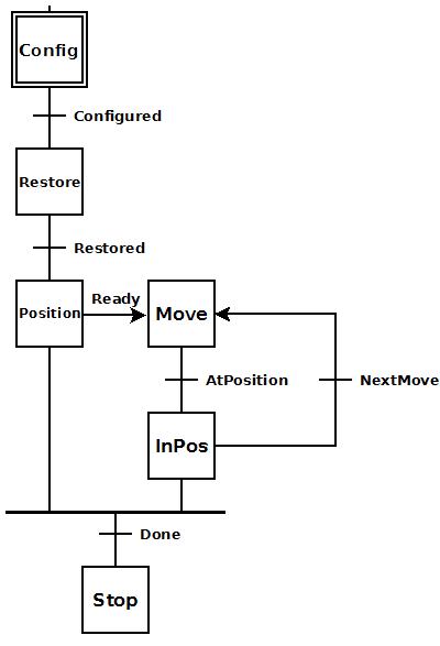 To the right is a stage diagram of a simple sequence
control that would move a motor to any number of positions. But it has
a feature of remembering the position of the motor in case there is a
power cycle. The output position is stored in a retentive memory location
and then written back.
To the right is a stage diagram of a simple sequence
control that would move a motor to any number of positions. But it has
a feature of remembering the position of the motor in case there is a
power cycle. The output position is stored in a retentive memory location
and then written back.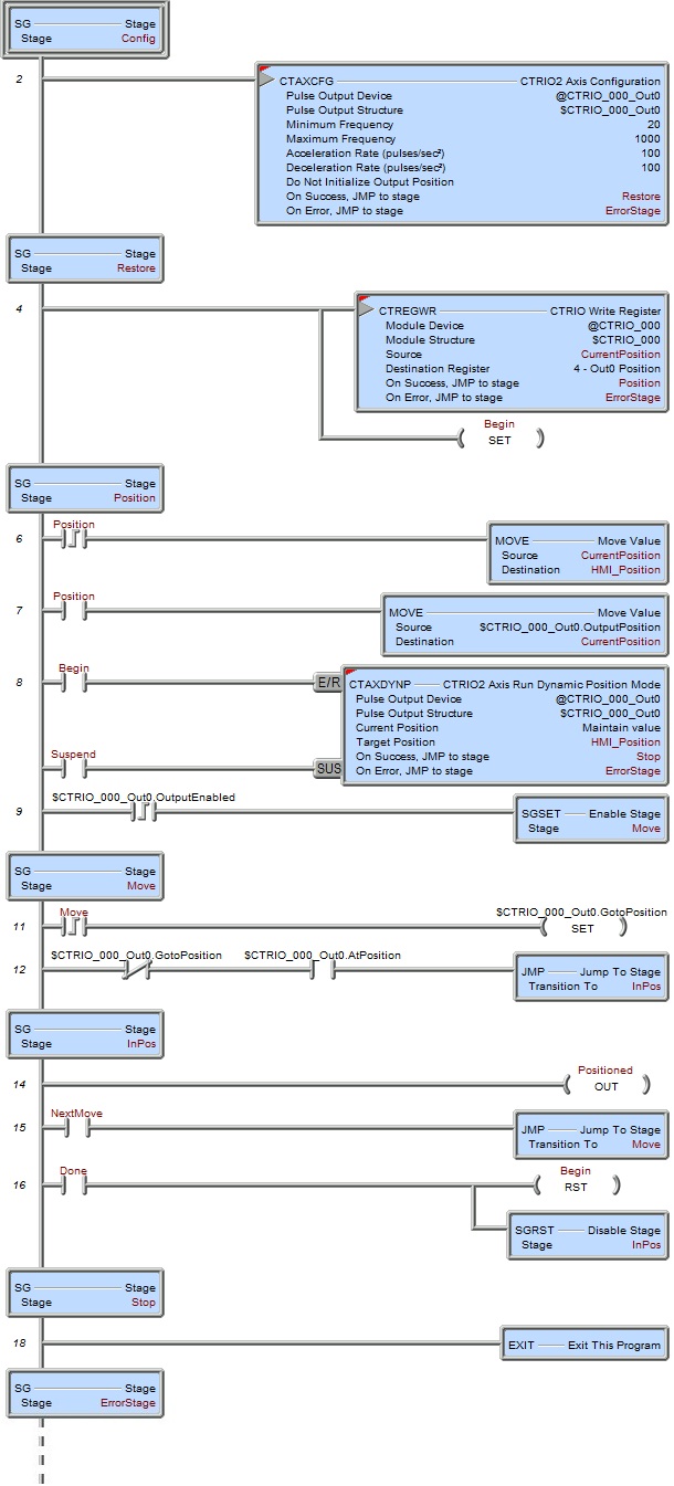 To the right is the ladder equivalent of the above
stage diagram that uses the CTREGWR instruction to restore the output
position of the CTRIO2 module after a power cycle. It only works for a
CTRIO2 since the CTAXCFG instruction cannot be used with a CTRIO.
To the right is the ladder equivalent of the above
stage diagram that uses the CTREGWR instruction to restore the output
position of the CTRIO2 module after a power cycle. It only works for a
CTRIO2 since the CTAXCFG instruction cannot be used with a CTRIO.