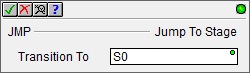
Topic: DMD0514

JMP - Jump To Stage


The Jump To Stage (JMP) instruction is used to transition from one stage to another stage by disabling the Stage which contains the JMP instruction, and enabling the target Stage specified in the JMP instruction.


When a Stage becomes disabled, on the next scan the disabled Stage executes Termination Logic where OUT coils are turned OFF.


For a complete discussion on Stage Programming and how to use the Stage programming instructions effectively, refer to the Help Topic on Stage Programming Concepts.


When the Jump To Stage (JMP) instruction is executed, it does NOT cause an immediate jump to the target Stage logic, it only disables the current Stage and enables the target Stage. The effect of this instruction will occur the next time those Stages are normally processed as part of the controller's scan. This means that any ladder logic instructions between the Jump To Stage (JMP) instruction and the end of the Stage will still be executed.


Note: All Stage programming instructions must be entered in a Program code block; Stage instructions cannot be placed in a Task code block.


Note: Stage programming instructions can only reference Stages in the same Program code block, they cannot reference Stages in a different Program code block.

Parameters:

Note: Use the F9 key (Element Browser) or Down-Arrow key (Auto-Complete) at any time to see a complete list of the memory locations that are valid in the current field of the instruction.


Transition To - designates the target Stage of the transition. The target Stage reference can be entered using its fully qualified name - for example MyProgram.S0 through MyProgram.S127 - or simply its local Stage number - S0 through S127.


See Also:

Stage Instructions in the Do-more Controllers


Related Topics:

Stage Programming Concepts

Introduction


Example 1 - A Simple 2-State Process


Stage Transition Instructions


Example 2 - A Lamp On/Off Controller


Example 3 - A Garage Door Opener


Review - Steps to Writing Successful Stage Programs


Example 1 of 2:

Description of a Jump To Stage Diagram:

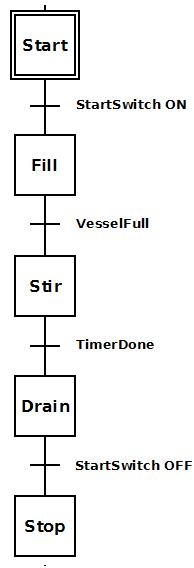
To the right is a stage diagram of a simple sequence control that would fill a vessel, stir its contents and then drain. It is good to imagine the sequence before actually writing the ladder logic.


Initially stage 'Start'  waits for StartSwitch to come ON. When StartSwitch comes ON, the process transitions to stage 'Fill'.


Stage 'Fill' fills the vessel. Once the vessel is full (VesselFull = ON), the process transitions to stage 'Stir'.


Stage 'Stir' stirs for a period of time. Once the time to stir is complete (TimerDone = ON), the process transitions to stage 'Drain'.


Stage 'Drain' empties the contents of the vessel. Once it is decided the vessel is drained, the StartSwitch is flipped OFF and the job is done.


Ladder Logic for the above Stage Diagram:

To the right is a ladder logic equivalent to the above stage diagram.


Once the Program code block containing this stage is first enabled to run, the initial stage 'Start' will be enabled because it is the initial stage (designated by the double border). None of the ladder logic in other stages ('Fill', 'Stir', 'Drain', 'Stop') is executed; only Rung 2. Once StartSwitch comes ON the JMP (Jump To Stage) instruction is executed. This instruction disables stage 'Start', and enables stage 'Fill' so that only the ladder logic in stage 'Fill' is being executed (i.e. Rungs 4-5).


Once stage 'Fill' is enabled Pump turns ON to power the pump motor so that product will begin to fill the vessel. Once the level detector input, VesselFull comes ON, the JMP instruction is executed. This instruction disables stage 'Fill' and enables stage 'Stir'. Also, since stage 'Fill' is now disabled, all of the OUT coils in that stage will be turned OFF (i.e. Pump will go OFF).


Once stage 'Stir' is enabled StirPaddle turns ON to power the stir-paddle motor so that the product can be stirred. Also TMR (StirTimer) begins to time. After 15 minutes of stir time, TimerDone bit comes ON which will execute the JMP instruction. This instruction disables stage 'Stir' and enables stage 'Drain'. Also, since stage 'Stir' is now disabled, all the OUT coils in that stage will be turned OFF and all the timers will be reset.


Once stage 'Drain' is enabled DrainValve turns ON to open the valve for the product to drain out of the vessel. Once StartSwitch turns OFF the JMP instruction is executed. This instruction disables stage 'Drain' and enables stage 'Stop'. Since stage 'Drain' is now disabled, all OUT coils in that stage will be turned OFF.


Once stage 'Stop' is enabled the EXIT instruction is executed and the Program code block containing this stage is exited.


If this sequence need be repeated, then the Program code block containing this stage would have to be run again.


It is possible, however, that instead of exiting the Program code block, the JMP instruction in stage 'Stop' could merely jump back to stage 'Start' using a JMP instruction instead of an EXIT. In this manner the stage would repeat indefinitely as long as the Program code block is not halted.


Example 2 of 2:


Copyright Host Engineering, Inc. ALL RIGHTS RESERVED