Topic: DMD0520
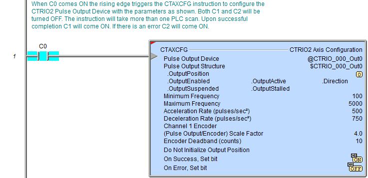
CTAXCFG - CTRIO2 Axis Configuration
Note: The CTAXCFG instruction can only be used with the CTRIO2 module.
The CTRIO2 Axis Configuration (CTAXCFG) instruction is used to define the characteristics of a profile that will be used by subsequent CTRIO2 Axis instructions.
The red triangle in the upper left corner indicates the CTRIO2 Axis Configuration (CTAXCFG) is a Fully Asynchronous instruction.
This instruction requires that the output channel that will be placed under Axis mode control is already configured for Pulse/Direction or CW/CCW pulse output mode by the System Configuration for the CTRIO.

Inputs:
The input is edge-triggered, meaning that each time this input logic transitions from OFF to ON, the CTRIO2 Axis Configuration (CTAXCFG) will run to completion, even if the input logic goes OFF before the operation is complete.
Parameters:
Note: Use the F9 key (Element Browser) or Down-Arrow key (Auto-Complete) at any time to see a complete list of the memory locations that are valid in the current field of the instruction.
 Pulse Output Device -
designates which of the pre-configured CTRIO2 Devices to interact with.
Before this instruction can select a Pulse
Output Device, a CTRIO2 Device must be configured with at least
one of its output channels setup for Pulse/Direction or CW/CCW pulse output
mode.
Pulse Output Device -
designates which of the pre-configured CTRIO2 Devices to interact with.
Before this instruction can select a Pulse
Output Device, a CTRIO2 Device must be configured with at least
one of its output channels setup for Pulse/Direction or CW/CCW pulse output
mode.
Part of the configuration for a device is assigning a name to the device. It is that name which will show up in the Pulse Output Device selection drop-down menu. For more information on configuring CTRIO2 devices go to the Module Configuration Section under System Configuration.
Note: no devices available - indicates that there are no CTRIO2 Devices that have been pre-configured to perform this instruction. Selecting 'create module' from the drop-down list will invoke the Create New Module Configuration dialog.
Note: create module - Selecting this will immediately pull up the System Configuration and allow the creation of a new module (see Module Configuration Section under System Configuration)
Pulse Output Structure - This field displays the name of the Pulse Output Structure that will be used by this instruction. This structure was created when the CTRIO2 module was configured during the Module Configuration phase.
Minimum Frequency - designates the starting frequency (in pulses per second) for the pulse output. This can be any positive constant value or any readable numeric location.
Maximum Frequency - designates the target frequency (in pulses per second) that the pulse output will ramp towards. This can be any positive constant value or any readable numeric location.
Acceleration Rate (pulses / sec2 ) - designates the rate at which the Minimum Frequency will to ramp toward the Maximum
Frequency. This can be any positive constant value or any readable numeric location.
Deceleration Rate (pulses / sec2 ) - designates the rate at which the Maximum Frequency will to ramp toward the Minimum Frequency. This can be any positive constant value or any readable numeric location.
Encoder Feedback - optionally selects which encoder feedback location to use and any required scaling of the encoder value.
None - no encoder feedback will be used.
Channel 1 - selects the encoder on CTRIO2 Channel 1
Channel 2 - selects the encoder on CTRIO2 Channel 2
Scale Factor (Pulse Output / Encoder) - designates optional scaling to account for different resolutions between the encoder and the stepper motor.
This value is derived by dividing the encoder resolution (in pulses per revolution, after adjusting for X2 or X4 pulse counts) by the stepper motor resolution (also in pulses per revolution).
This can be any positive constant value between 9.809089E-45 to 2,147,483,647 or any readable numeric location.
Encoder Deadband (counts) - designates a number of pulses to use as a deadband around the target pulse count. This is helpful to prevent jitter of the stepper motor.
This count value is applied equally above and below the target pulse count. A good minimum value is the number of encoder pulses that are generated by one stepper pulse, mathematically this equates to (2 / Scale Factor).
This can be any positive constant value or any readable numeric location.
Initialize Output Position - optionally specifies whether to initialize the current position value (.OutputPosition) to the supplied value when this instruction is executed. This can be any positive or negative constant value or any readable numeric location.
On Success - designates which of the following actions to take if the CTRIO2 Axis Configuration (CTAXCFG) operation is successful, that is, the profile description is successfully loaded into the CTRIO2's memory, and the designated pulse output is in Axis mode.
SET BIT - The specific BIT location will be turned OFF when the CTRIO2 Axis Configuration (CTAXCFG) instruction is first enabled, and then SET ON if the operation is successful. This value can be any writable bit location.
JMP to Stage - JMP to the specified Stage. The target Stage must be in the same Program code block as the CTRIO2 Axis Configuration (CTAXCFG) instruction, you cannot specify a Stage in a different Program code block. This selection will function like a standalone Jump to Stage instruction. Click here for more information on the Jump To Stage instruction.
On Error - designates which
of the following two actions to take if the CTRIO2 Axis Configuration
operation is unsuccessful. For example if this instruction tries to target
a CTRIO module (not a CTRIO2), or if the specified output device is not
configured as a Pulse Output.
SET BIT - The specific BIT location will be turned OFF when the CTRIO2 Axis Configuration (CTAXCFG) instruction is first enabled, and then SET ON if the operation is unsuccessful. This value can be any writable bit location.
JMP to Stage - JMP to the specified Stage. The target Stage must be in the same Program code block as the CTRIO2 Axis Configuration (CTAXCFG) instruction, you cannot specify a Stage in a different Program code block. This selection will function the same as a standalone Jump to Stage instruction. Click here for more information on the Jump To Stage instruction.
Note: any time the On Error condition occurs, the CTRIO2 generates an Error Code that can be read in the <Module Name>.ErrorCode (Module Name is the name assigned to the CTRIO2 in the Module Configuration). The List of Error Code values (in decimal) follows:
|
Error Code |
Description |
|
000 |
No Error |
|
100 |
Specified command code is unknown or unsupported |
|
101 |
File number not found in the file system |
|
102 |
File type is incorrect for specified output function |
|
103 |
Profile type is unknown |
|
104 |
Specified input is not configured as a limit on this output |
|
105 |
Specified limit input edge is out of range |
|
106 |
Specified input function is unconfigured or invalid |
|
107 |
Specified input function number is out of range |
|
108 |
Specified preset function is invalid |
|
109 |
Preset table is full |
|
110 |
Specified Table entry is out of range |
|
111 |
Specified register number is out of range |
|
112 |
Specified register is an unconfigured input or output |
|
113 |
Specified output is not configured as a limit on this output |
|
114 |
Specified preset function invalid in PLS table |
|
115 |
Specified PLS function invalid in preset table |
|
116 |
PLS table entries overlap |
|
117 |
Attempted to use axis function when pulse output is not in Axis Mode |
|
118 |
Specified output isn't a pulse output |
Status Display:
The Status display of the CTRIO2 Axis Configuration (CTAXCFG) instruction shows:
Values: .OutputPosition, Minimum Frequency, Maximum Frequency, Acceleration Rate, Deceleration Rate, (Pulse Output/Encoder) Scale Factor (if configured), Encoder Deadband (if configured), Initialize Output Position (if configured)
Highlights: .OutputEnabled, .OutputActive, .Direction, .OutputSuspended, .OutputStalled bits
ON/OFF: On Success, On Error bits

CTRIO2 Structure Field Care-Abouts:
The following is a list of the"dot" fields of the CTRIO2 structure that are programmatically used with the CTRIO2 Axis Configuration (CTAXCFG) instruction. To see a complete listing of all CTRIO structures and members, goto the Project Browser --> Configuration --> Memory --> I/O --> Specialty.
COLOR KEY
Blue: CTRIO2 Input
Maroon: CTRIO2 Output
Black: CTRIO2 Module
Silver: Not used for this instruction
Note: The red "x" is the digit 0, 1, 2, or 3.
|
CTRIO_000 |
CTAXCFG |
||
|
MEMBER |
R/W |
TYPE |
DESCRIPTION |
|
_CxFx.AtResetValue |
RO |
Bit |
ON if CxFx count is at reset value |
|
_CxFx.CaptureComplete |
|
|
|
|
_CxFx.CapturedStart |
|
|
|
|
_CxFx.CountCaptured |
|
|
|
|
_CxFx.EnableCapture |
|
|
|
|
_CxFx.fReg1 |
RO |
Dword |
If floating-point scaling is configured for CxFx in CTRIO2: Floating-point scaled value; otherwise, number has no meaning |
|
_CxFx.fReg2 |
|
|
|
|
_CxFx.iReg1 |
RO |
Dword |
If integer or BCD scaling is configured for CxFx in CTRIO2: Signed-integer or BCD scaled value; otherwise, signed-integer raw count |
|
_CxFx.iReg2 |
RO |
Dword |
If any scaling is configured for CxFx in CTRIO2: Signed-integer raw count; otherwise, number has no meaning |
|
_CxFx.Output |
|
|
|
|
_CxFx.Reset |
R/W |
Bit |
Set ON to reset CxFx count |
|
_CxFx.Timeout |
|
|
|
|
_Outx.AtPosition |
RO |
Bit |
If CTAXDYNP is used: ON when CTRIO2 has reached Target Position |
|
_Outx.AtVelocity |
RO |
Bit |
If CTAXDYNV is used: ON when CTRIO2 has reached Frequency |
|
_Outx.Direction |
RO |
Bit |
If CTAXLIMT is used: ON when its DIR
input was ON before the E/R
input came ON & motor is moving counter-clockwise |
|
_Outx.EnableOutput |
|
|
|
|
_Outx.GotoPosition |
R/W |
Bit |
If CTAXDYNP is used: Set ON to initiate a move; CTRIO2 resets OFF when moving |
|
_Outx.Output |
|
|
|
|
_Outx.OutputActive |
RO |
Bit |
ON when CTRIO2 output is generating pulses |
|
_Outx.OutputEnabled |
RO |
Bit |
ON when E/R input comes ON which enables CTRIO2 output |
|
_Outx.OutputPosition |
RO |
Dword |
CTRIO2 output raw position (or encoder feedback position if CTAXCFG is configured as such) |
|
_Outx.OutputStalled |
RO |
Bit |
ON if CTRIO2 output cannot generate pulses because its scantime is too high |
|
_Outx.OutputSuspended |
RO |
Bit |
If using CTAXDYNP, CTAXDYNV, CTAXLIMT or CTAXTRAP:
ON when their SUS input comes
ON which suspends the CTRIO2 output |
|
_Outx.OutputVelocity |
RO |
Dword |
Current pulses per second rate being output by the CTRIO2 |
|
_Outx.TableComplete |
|
|
|
|
.ErrorCode |
RO |
Word |
Last CTRIO2 error code |
|
.Mode |
RO |
Word |
Indicates CTRIO2 mode: 2 = RUN; 1 = PROGRAM |
|
.ScanTime |
RO |
Word |
CTRIO2 scantime in microseconds |
|
.MaxScanTime |
RO |
Word |
Maximum CTRIO2 scantime in microseconds |
|
.InputState |
RO |
Word |
Upper byte is not used. Lower byte's nibbles indicate CTRIO2's channel's input's state in order: .ChxD, .ChxC, .ChxB, .ChxA. It is a composite of these members |
|
.OutputState |
RO |
Word |
Each nibble indicates a CTRIO2 output configuration and state: .OutxType, .OutxDiscOn, .OutxDiscEnabled, .OutxPulseActive. It is a composite of these members |
|
.ChxA |
RO |
Bit |
ON when CTRIO2 Channel x Input A is ON |
|
.ChxB |
RO |
Bit |
ON when CTRIO2 Channel x Input B is ON |
|
.ChxC |
RO |
Bit |
ON when CTRIO2 Channel x Input C is ON |
|
.ChxD |
RO |
Bit |
ON when CTRIO2 Channel x Input D is ON |
|
.OutxType |
RO |
Bit |
Configuration: ON if CTRIO2 output x is configured for pulse output |
|
.OutxDiscOn |
RO |
Bit |
Status: ON if CTRIO2 output x logic is ON (if output x is enabled then the physical output will also be ON) |
|
.OutxDiscEnabled |
RO |
Bit |
Configuration: ON if CTRIO2 output x is configured for discrete output |
|
.OutxPulseActive |
RO |
Bit |
Status: ON if CTRIO2 output x is generating pulses |
See Also:
CTRIO2 Axis Configuration
 To the right is a stage diagram of a simple sequence
control that would move a motor to any number of positions and stop.
To the right is a stage diagram of a simple sequence
control that would move a motor to any number of positions and stop. To the right is the ladder equivalent of the above stage diagram
that uses the CTAXDYNP instruction which will move a stepper motor attached
to the CTRIO2's pulse output to any number of subsequent positions utilizing
an axis configuration (CTAXCFG) profile, and then stop. Click
To the right is the ladder equivalent of the above stage diagram
that uses the CTAXDYNP instruction which will move a stepper motor attached
to the CTRIO2's pulse output to any number of subsequent positions utilizing
an axis configuration (CTAXCFG) profile, and then stop. Click