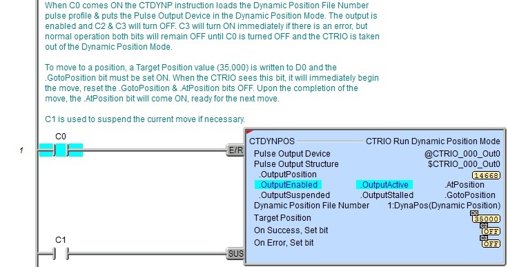
DMD0516
CTDYNPOS - CTRIO Run Dynamic Position Mode
The CTRIO Run Dynamic Position Mode (CTDYNPOS) instruction is used to select and load a one of the pre-configured Dynamic Position or Dynamic Position Plus Profiles in the System Configuration for the CTRIO, and put the Pulse Output Device into Dynamic Position Mode, allowing successive moves to be easily commanded. Once in Dynamic Position Mode, moves are commanded by changing the Target Position value and setting (one-shot) the .GotoPosition bit for the Pulse Output Device. The moves will execute using the parameters defined in the specified profile.
The red triangle in the upper left corner indicates the CTRIO Run Dynamic Positioin Mode (CTDYNPOS) is a Fully Asynchronous instruction.
Note: The CTDYNPOS instruction can be used with both the CTRIO and CTRIO2 modules.

Inputs:
The first input (E/R) is the Enable / Reset input. When this input logic comes ON the Pulse Output Device is placed in the "Dynamic Positioning Mode", the specified Dynamic Position File Number will be loaded, the current position value will be set to 0 (e.g. .OutputPosition = 0) and the Output will be enabled (.OutputEnabled = ON). It must remain ON until all desired positions have been reached. When this input logic goes OFF the Pulse Output Device is removed from "Dynamic Positioning Mode", the Output will be disabled (.OutputEnabled = OFF) and the On Success or On Error bit is set.
The second input (SUS) is the Suspend input. This input has different effects on the CTRIO output depending on the pulse profile specified by the Dynamic Position File Number parameter:
|
DEVICE |
CTRIO/CTRIO2 PULSE PROFILE |
EFFECT |
|
CTRIO2 |
Dynamic Positioning |
When SUS input comes ON the CTRIO2 will abruptly stop emitting output pulses. When SUS input returns to OFF the CTRIO2 will abruptly start emitting the remaining output pulses. (Refer to Abrupt Suspend picture below) |
|
Dynamic Positioning Plus (CTRIO2) |
When SUS
input comes ON, the CTRIO2 will ramp down to zero using the Decel
Rate specified in the Dynamic
Positioning Plus (CTRIO2) profile. (Refer to Deceleration Suspend picture below) | |
|
CTRIO |
Dynamic Positioning |
When SUS input comes ON the CTRIO will abruptly stop emitting output pulses. When SUS input returns to OFF the CTRIO will abruptly start emitting the remaining output pulses. (Refer to Abrupt Suspend picture below) |
|
Dynamic Positioning Plus (CTRIO2) |
Note: Attempting to use this pulse profile with the CTRIO will result in an Error 103 (see chart below). |
Abrupt Suspend

Deceleration Suspend

Parameters:
Note: Use the F9 key (Element Browser) or Down-Arrow key (Auto-Complete) at any time to see a complete list of the memory locations that are valid in the current field of the instruction.
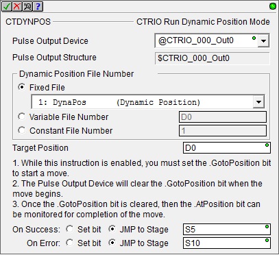 Pulse Output Device -
designates which of the pre-configured CTRIO Devices to interact with.
Before this instruction can select a Pulse
Output Device, a CTRIO Device must be configured with at least
one of its output channels setup for Pulse/Direction
or CW/CCW pulse output mode.
Pulse Output Device -
designates which of the pre-configured CTRIO Devices to interact with.
Before this instruction can select a Pulse
Output Device, a CTRIO Device must be configured with at least
one of its output channels setup for Pulse/Direction
or CW/CCW pulse output mode.
Part of the configuration for a device is assigning a name to the device. It is that name which will show up in the Pulse Output Device selection drop-down menu. For more information on configuring CTRIO devices go to the Module Configuration Section under System Configuration.
Note: no devices available - indicates that there are no CTRIO Devices that have been pre-configured to perform this instruction.
Note: create module - Selecting this will immediately pull up the System Configuration and allow the creation of a new module (see Module Configuration Section under System Configuration.)
Pulse Output Structure -
Dynamic Position File Number
- designates which Dynamic Position Profile to Run.
The profile can be specified in one of the following three ways:
-
Fixed File - displays a list of the Dynamic Position Profiles that were read from the CTRIO module during the Module Configuration phase. Select the desired profile from the list. Available Profiles:
PROFILE
(Silver text indicates the profile cannot be used with CTDYNPOS)
CTRIO
CTRIO2
Trapezoid
S-Curve
Symmetrical S-Curve
Dynamic Positioning
Yes
Yes
Dynamic Velocity
Home Search
Free Form
Dynamic Positioning Plus (CTRIO2)
No
Yes
Trapezoid Plus (CTRIO2)
Trapezoid w/Limits (CTRIO2)
Variable File Number - designates a location in the Do-more controller where the Dynamic Position Profile number will be read. This can be any readable numeric location.
Constant File Number - specify the Dynamic Position Profile number as a constant number from 1 to 255.
Target Position - specifies the next target position value for the Dynamic Position Profile. The direction (clockwise or counter-clockwise) is inferred from the difference between the Target Position and the current position (.OutputPosition), that is, if the Target Position is greater than the current position, pulses for a clockwise move are emitted; if the Target Position is less than the current position, pulses for a counter-clockwise move are emitted. This can be any positive or negative constant value or any readable numeric location.
On Success - designates which of the following actions to take if the CTRIO Run Dynamic Position Mode operation is successful.
Note: On Success is not indicated upon the completion of every move (.GotoPosition bit transitioning from OFF to ON). Instead, the .AtPosition bit of the Pulse Output Device structure is the proper feedback bit for each move. In other words, while the E/R (Enable / Reset) input is ON, the Pulse Output Device is considered in the "Dynamic Position Mode". When the E/R (Enable / Reset) input goes OFF, this is when On Success will be indicated.
Set bit - The specific BIT location will turn OFF when the CTRIO Run Dynamic Position Mode (CTDYNPOS) instruction is first enabled, and then SET ON when the instruction is disabled, if the operation is successful. This value can be any writable bit location.
JMP to Stage - JMP to the specified Stage. The target Stage must be in the same Program code block as the CTRIO Run Dynamic Position Mode (CTDYNPOS) instruction, you cannot specify a Stage in a different Program code block. This selection will function like a standalone Jump to Stage instruction. Click here for more information on the Jump To Stage instruction.
On Error - designates which
of the following two actions to take if the CTRIO Run Dynamic Position
Mode (CTDYNPOS) operation is unsuccessful. For example if the specified
Dynamic Position Profile is missing,
or the specified Profile number is the wrong type for a Pulse
Output.
Set bit - The specific BIT location will turn OFF when the CTRIO Run Dynamic Position Mode (CTDYNPOS) instruction is first enabled, and then SET ON if the operation is unsuccessful. This value can be any writable bit location.
JMP to Stage - JMP to the specified Stage. The target Stage must be in the same Program code block as the CTRIO Run Dynamic Position Mode (CTDYNPOS) instruction, you cannot specify a Stage in a different Program code block. This selection will function like a standalone Jump to Stage instruction. Click here for more information on the Jump To Stage instruction.
Note: any time the On Error condition occurs, the CTRIO generates an Error Code that can be read in the <Module Name>.ErrorCode (Module Name is the name assigned to the CTRIO in the Module Configuration). The List of Error Code values (in decimal) follows:
|
Error Code |
Description |
|
000 |
No Error |
|
100 |
Specified command code is unknown or unsupported |
|
101 |
File number not found in the file system |
|
102 |
File type is incorrect for specified output function |
|
103 |
Profile type is unknown |
|
104 |
Specified input is not configured as a limit on this output |
|
105 |
Specified limit input edge is out of range |
|
106 |
Specified input function is unconfigured or invalid |
|
107 |
Specified input function number is out of range |
|
108 |
Specified preset function is invalid |
|
109 |
Preset table is full |
|
110 |
Specified Table entry is out of range |
|
111 |
Specified register number is out of range |
|
112 |
Specified register is an unconfigured input or output |
|
113 |
Specified output is not configured as a limit on this output |
|
114 |
Specified preset function invalid in PLS table |
|
115 |
Specified PLS function invalid in preset table |
|
116 |
PLS table entries overlap |
|
117 |
Attempted to use axis function when pulse output is not in Axis Mode |
|
118 |
Specified output isn't a pulse output |
Status Display:
The Status display of the CTRIO Run Dynamic Position Mode (CTDYNPOS) instruction shows:
Values: .OutputPosition, Target Position, Dynamic Position File Number
Highlights: .OutputEnabled, .OutputActive, .AtPosition, .OutputSuspended, .OutputStalled, .GotoPosition bits.
ON/OFF: On Success, On Error bits

CTRIO Structure Field Care-Abouts:
The following is a list of the"dot" fields of the CTRIO structure that are programmatically used with the CTRIO Run Dynamic Position Mode (CTDYNPOS) instruction. To see a complete listing of all CTRIO structures and members, goto the Project Browser --> Configuration --> Memory --> I/O --> Specialty.
COLOR KEY
Blue: CTRIO Input
Maroon: CTRIO Output
Black: CTRIO Module
Silver: Not used for this instruction
Note: The red "x" is the digit 0, 1, 2, or 3.
|
CTRIO_000 |
CTDYNPOS |
||
|
MEMBER |
R/W |
TYPE |
DESCRIPTION |
|
_CxFx.AtResetValue |
RO |
Bit |
ON if CxFx count is at reset value |
|
_CxFx.CaptureComplete |
|
|
|
|
_CxFx.CapturedStart |
|
|
|
|
_CxFx.CountCaptured |
|
|
|
|
_CxFx.EnableCapture |
|
|
|
|
_CxFx.fReg1 |
RO |
Dword |
If floating-point scaling is configured for CxFx in CTRIO2: Floating-point scaled value; otherwise, number has no meaning |
|
_CxFx.fReg2 |
|
|
|
|
_CxFx.iReg1 |
RO |
Dword |
If integer or BCD scaling is configured for CxFx in CTRIO2: Signed-integer or BCD scaled value; otherwise, signed-integer raw count |
|
_CxFx.iReg2 |
RO |
Dword |
If any scaling is configured for CxFx in CTRIO2: Signed-integer raw count; otherwise, number has no meaning |
|
_CxFx.Output |
|
|
|
|
_CxFx.Reset |
R/W |
Bit |
ON to reset CxFx count |
|
_CxFx.Timeout |
|
|
|
|
_Outx.AtPosition |
RO |
Bit |
ON when CTRIO has reached Target Position |
|
_Outx.AtVelocity |
|
|
|
|
_Outx.Direction |
RO |
Bit |
If using CTRIO2: ON when motor is moving counter-clockwise |
|
_Outx.EnableOutput |
|
|
|
|
_Outx.GotoPosition |
R/W |
Bit |
Set ON to initiate a move; CTRIO resets OFF when moving |
|
_Outx.Output |
|
|
|
|
_Outx.OutputActive |
RO |
Bit |
ON when CTRIO output is generating pulses |
|
_Outx.OutputEnabled |
RO |
Bit |
ON when E/R input comes ON which enables CTRIO output |
|
_Outx.OutputPosition |
RO |
Dword |
Output raw position (or encoder feedback position if using a Dynamic Position Plus (CTRIO2) profile and "Use Encoder for Position" is selected) |
|
_Outx.OutputStalled |
RO |
Bit |
ON if CTRIO output cannot generate pulses because its scantime is too high |
|
_Outx.OutputSuspended |
RO |
Bit |
ON when the SUS input comes ON which suspends the CTRIO output |
|
_Outx.OutputVelocity |
RO |
Dword |
If using CTRIO2: Current pulses per second rate being output by the CTRIO2 |
|
_Outx.TableComplete |
|
|
|
|
.ErrorCode |
RO |
Word |
Last CTRIO error code |
|
.Mode |
RO |
Word |
Indicates CTRIO mode: 2 = RUN; 1 = PROGRAM |
|
.ScanTime |
RO |
Word |
CTRIO scantime in microseconds |
|
.MaxScanTime |
RO |
Word |
Maximum CTRIO scantime in microseconds |
|
.InputState |
RO |
Word |
Upper byte is not used. Lower byte's nibbles indicate CTRIO's channel's input's state in order: .ChxD, .ChxC, .ChxB, .ChxA. It is a composite of these members |
|
.OutputState |
RO |
Word |
Each nibble indicates a CTRIO output configuration and state: .OutxType, .OutxDiscOn, .OutxDiscEnabled, .OutxPulseActive. It is a composite of these members |
|
.ChxA |
RO |
Bit |
ON when CTRIO Channel x Input A is ON |
|
.ChxB |
RO |
Bit |
ON when CTRIO Channel x Input B is ON |
|
.ChxC |
RO |
Bit |
ON when CTRIO Channel x Input C is ON |
|
.ChxD |
RO |
Bit |
ON when CTRIO Channel x Input D is ON |
|
.OutxType |
RO |
Bit |
Configuration: ON if CTRIO output x is configured for pulse output |
|
.OutxDiscOn |
RO |
Bit |
Status: ON if CTRIO output x logic is ON (if output x is enabled then the physical output will also be ON) |
|
.OutxDiscEnabled |
RO |
Bit |
Configuration: ON if CTRIO output x is configured for discrete output |
|
.OutxPulseActive |
RO |
Bit |
Status: ON if CTRIO output x is generating pulses |
See Also:
CTDYNPOS - CTRIO Run Dynamic Position Mode
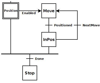 To the right is a stage diagram
of a simple sequence control that would move a motor to any number of
positions and stop.
To the right is a stage diagram
of a simple sequence control that would move a motor to any number of
positions and stop. To the right is the ladder equivalent of the above
stage diagram that uses the CTDYNPOS instruction which will move a stepper
motor attached to the CTRIO's pulse output to any number of subsequent
positions utilizing a pre-configured pulse profile, and then stop.
To the right is the ladder equivalent of the above
stage diagram that uses the CTDYNPOS instruction which will move a stepper
motor attached to the CTRIO's pulse output to any number of subsequent
positions utilizing a pre-configured pulse profile, and then stop.