DMD0531
CTTBLADD - CTRIO Add Entry to Preset Table
The CTRIO Add Entry to Preset Table (CTTBLADD) instruction is used to add an entry to the table that is currently loaded for the specified CTRIO Discrete Output or create one in CTRIO memory for immediate use.
This instruction implements the following CTRIO functions
Add Table Entry
Initialize Table
Initialize Table on Reset
Note: Changes made to CTRIO Preset tables using this instruction do not change any of the Preset tables configured in the System Configuration for the CTRIO. They are temporary and are lost on a power-cycle of the CTRIO or if some other table is loaded in their place. The changes cannot be viewed, for example, in the PLC --> System Configuration.
The red triangle in the upper left corner indicates the CTRIO Add Entry to Preset Table (CTTBLADD) is a Fully Asynchronous instruction.
Note: The CTTBLADD instruction can be used with both the CTRIO and CTRIO2 module.

Inputs:
The input is edge-triggered,
meaning that each time this input logic transitions from OFF to ON, the
CTRIO Add Entry to Preset Table (CTTBLADD) will:
Add an entry to the currently loaded Output Preset table on the CTRIO Discrete Output Device, or initialize one in CTRIO memory for immediate use
Run to completion, even if the input logic goes OFF before the operation is complete
Parameters:
Note: Use the F9 key (Element Browser) at any time to see a complete list of the memory locations that are valid in the current field of the instruction.
 Discrete Output Device
- designates which of the pre-configured CTRIO Discrete Output Devices
to interact with. Before this instruction can select a Discrete Output
Device, a CTRIO Device must be configured with at least one of its output
channels setup for Discrete output mode.
Discrete Output Device
- designates which of the pre-configured CTRIO Discrete Output Devices
to interact with. Before this instruction can select a Discrete Output
Device, a CTRIO Device must be configured with at least one of its output
channels setup for Discrete output mode.
Part of the configuration for a device is assigning a name to the device. It is that name which will show up in the Discrete Output Device selection drop-down menu. For more information on configuring CTRIO devices go to the Module Configuration Section under System Configuration.
Note: no devices available - indicates that there are no CTRIO Devices that have been pre-configured to perform this instruction.
Discrete Output Structure -
Initialize First - optionally clear any entries in the currently loaded table before adding the preset specified in this instruction
Note: enabling this option implements CTRIO function Initialize
Table
Use on Next Reset - (only valid with Initialize First) - selection will perform the initialization and adding of the Preset when the count value is reset.
Note: enabling this option implements CTRIO function Initialize Table on Reset
Preset
- specifies the count at which the desired action will take place. This
can be any positive or negative constant value, or any readable numeric
location.
Entry Type - designates which of the following actions to perform at the specified Preset:
0 - Set Output ON
1 - Set Output OFF
2 - Pulse Output ON
3 - Pulse Output OFF
4 - Toggle Output
5 - Reset Count
Pulse Time - (only valid Entry Type is 2 or 3) - Specifies the duration of the pulse, in milliseconds, when the Entry Type is set to 2 (Pulse Output ON) or 3 (Pulse Output OFF). This can be any constant value from 0 to 65535, or any readable numeric location.
On Success - designates which of the following actions to take if the CTRIO Add Entry to Preset Table operation is successful.
SET BIT - The specific BIT location will be turned OFF when the CTRIO Add Entry to Preset Table (CTTBLADD) instruction is first enabled, and then SET ON if the operation is successful. This value can be any writable bit location.
JMP to Stage - JMP to the specified Stage. The target Stage must be in the same Program code block as the CTRIO Add Entry to Preset Table (CTTBLADD) instruction, you cannot specify a Stage in a different Program code block. This selection will function like a standalone Jump to Stage instruction. Click here for more information on the Jump To Stage instruction.
On Error - designates which of the following two actions to take if the CTRIO Add Entry to Preset Table operation is unsuccessful.
SET BIT - The specific BIT location will be turned OFF when the CTRIO Add Entry to Preset Table (CTTBLADD) instruction is first enabled, and then SET ON if the operation is unsuccessful. This value can be any writable bit location.
JMP to Stage - JMP to the specified Stage. The target Stage must be in the same Program code block as the CTRIO Add Entry to Preset Table (CTTBLADD) instruction, you cannot specify a Stage in a different Program code block. This selection will function the same as a standalone Jump to Stage instruction. Click here for more information on the Jump To Stage instruction.
Note: any time the On Error condition occurs, the CTRIO generates an Error Code that can be read in the <Module Name>.ErrorCode (Module Name is the name assigned to the CTRIO in the Module Configuration). The List of Error Code values (in decimal) follows:
|
Error Code |
Description |
|
000 |
No Error |
|
100 |
Specified command code is unknown or unsupported |
|
101 |
File number not found in the file system |
|
102 |
File type is incorrect for specified output function |
|
103 |
Profile type is unknown |
|
104 |
Specified input is not configured as a limit on this output |
|
105 |
Specified limit input edge is out of range |
|
106 |
Specified input function is unconfigured or invalid |
|
107 |
Specified input function number is out of range |
|
108 |
Specified preset function is invalid |
|
109 |
Preset table is full |
|
110 |
Specified Table entry is out of range |
|
111 |
Specified register number is out of range |
|
112 |
Specified register is an unconfigured input or output |
|
113 |
Specified output is not configured as a limit on this output |
|
114 |
Specified preset function invalid in PLS table |
|
115 |
Specified PLS function invalid in preset table |
|
116 |
PLS table entries overlap |
|
117 |
Attempted to use axis function when pulse output is not in Axis Mode |
|
118 |
Specified output isn't a pulse output |
Status Display:
The Status display of the CTRIO Run Position Mode (CTRUNPOS) instruction shows:
Values: Preset, Pulse Time (ms)
Highlight: .OutputEnabled, .TableComplete bits
ON/OFF: On Success, On Error bits

CTRIO Structure Field Care-Abouts:
The following is a list of the"dot" fields of the CTRIO structure that are programmatically used with the CTRIO Add Entry to Preset Table (CTTBLADD) instruction. To see a complete listing of all CTRIO structures and members, goto the Project Browser --> Configuration --> Memory --> I/O --> Specialty.
COLOR KEY
Blue: CTRIO Input
Maroon: CTRIO Output
Black: CTRIO Module
Silver: Not used for this instruction
Note: The red "x" is the digit 0, 1, 2, or 3.
|
CTRIO_000 |
CTTBLADD |
||
|
MEMBER |
R/W |
TYPE |
DESCRIPTION |
|
_CxFx.AtResetValue |
RO |
Bit |
|
|
_CxFx.CaptureComplete |
|
|
|
|
_CxFx.CapturedStart |
|
|
|
|
_CxFx.CountCaptured |
|
|
|
|
_CxFx.EnableCapture |
|
|
|
|
_CxFx.fReg1 |
RO |
Dword |
If floating-point scaling is configured for CxFx in CTRIO: Floating-point scaled value; otherwise, number has no meaning |
|
_CxFx.fReg2 |
|
|
|
|
_CxFx.iReg1 |
RO |
Dword |
If integer or BCD scaling is configured for CxFx in CTRIO: Signed-integer or BCD scaled value; otherwise, signed-integer raw count |
|
_CxFx.iReg2 |
RO |
Dword |
If any scaling is configured for CxFx in CTRIO: Signed-integer raw count; otherwise, number has no meaning |
|
_CxFx.Output |
|
|
|
|
_CxFx.Reset |
R/W |
Bit |
Set ON to reset CxFx count |
|
_CxFx.Timeout |
|
|
|
|
_Outx.AtPosition |
|
|
|
|
_Outx.AtVelocity |
|
|
|
|
_Outx.Direction |
|
|
|
|
_Outx.EnableOutput |
R/W |
Bit |
Set ON to enable the CTRIO discrete output that will operate with the Preset Table |
|
_Outx.GotoPosition |
|
|
|
|
_Outx.Output |
|
|
|
|
_Outx.OutputActive |
|
|
|
|
_Outx.OutputEnabled |
RO |
Bit |
ON when CTRIO output has been enabled |
|
_Outx.OutputPosition |
|
|
|
|
_Outx.OutputStalled |
|
|
|
|
_Outx.OutputSuspended |
|
|
|
|
_Outx.OutputVelocity |
|
|
|
|
_Outx.TableComplete |
RO |
Bit |
ON when the last entry in the Preset Table has been executed (i.e. the count is higher than the last preset in the table) |
|
.ErrorCode |
RO |
Word |
Last CTRIO error code |
|
.Mode |
RO |
Word |
Indicates CTRIO mode: 2 = RUN; 1 = PROGRAM |
|
.ScanTime |
RO |
Word |
CTRIO scantime in microseconds |
|
.MaxScanTime |
RO |
Word |
Maximum CTRIO scantime in microseconds |
|
.InputState |
RO |
Word |
Upper byte is not used. Lower byte's nibbles indicate CTRIO's channel's input's state in order: .ChxD, .ChxC, .ChxB, .ChxA. It is a composite of these members |
|
.OutputState |
RO |
Word |
Each nibble indicates a CTRIO output configuration and state: .OutxType, .OutxDiscOn, .OutxDiscEnabled, .OutxPulseActive. It is a composite of these members |
|
.ChxA |
RO |
Bit |
ON when CTRIO Channel x Input A is ON |
|
.ChxB |
RO |
Bit |
ON when CTRIO Channel x Input B is ON |
|
.ChxC |
RO |
Bit |
ON when CTRIO Channel x Input C is ON |
|
.ChxD |
RO |
Bit |
ON when CTRIO Channel x Input D is ON |
|
.OutxType |
RO |
Bit |
Configuration: ON if CTRIO output x is configured for pulse output |
|
.OutxDiscOn |
RO |
Bit |
Status: ON if CTRIO output x logic is ON (if output x is enabled then the physical output will also be ON) |
|
.OutxDiscEnabled |
RO |
Bit |
Configuration: ON if CTRIO output x is configured for discrete output |
|
.OutxPulseActive |
RO |
Bit |
Status: ON if CTRIO output x is generating pulses |
See Also:
CTTBLADD - CTRIO Add Entry to Preset Table
Example 1 of 2:
Description of a Typical CTRIO Add Entry to Preset Table (CTTBLADD) Stage Diagram:
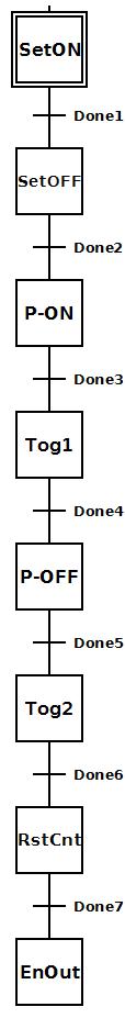 To the right is a stage diagram of a simple sequence
control that would create a Discrete Table for a CTRIO output and add
7 entries to it.
To the right is a stage diagram of a simple sequence
control that would create a Discrete Table for a CTRIO output and add
7 entries to it.
Initially the SetON stage creates the Discrete Table and adds the first entry to set the output ON at a certain preset value.
SetOFF adds 2nd entry to set the output OFF at a certain preset.
P-ON (PulseON) adds 3rd entry to pulse the output ON for a time period at a certain preset.
Tog1 (Toggle1) adds 4th entry to toggle the output from OFF to ON at a certain preset.
P-OFF (PulseOFF) adds 5th entry to pulse the output OFF for a time period at a certain preset.
Tog2 (Toggle2) adds 6th entry to toggle the output from ON to OFF at a certain preset.
RstCnt (ResetCount) adds 7th and final entry to reset the count at a certain preset.
EnOut (EnableOutput) enables the output to work and exits.
Description of a Typical CTRIO Add Entry to Preset Table (CTTBLADD) Stage Ladder:
 To the right is the ladder equivalent of the above
stage diagram of a simple sequence control that would create a Discrete
Table for a CTRIO output and add 7 entries to it.
To the right is the ladder equivalent of the above
stage diagram of a simple sequence control that would create a Discrete
Table for a CTRIO output and add 7 entries to it.
This example presupposes the existence of the following System Configuration for the CTRIO (PLC --> System Configuration --> Module Configuration(s) --> CTRIO_000 -->):
Configure I/O -->
Channel 1 --> Quad Counter.
Outputs --> Out2 --> Discrete on Ch1/Fn1.
A quadrature encoder is wired to CTRIO's Channel 1 Input A & B.
A discrete device that utilizes the CTRIO's Output is wired to CTRIO's Output 2.
Initially the SetON stage creates the Discrete Table and adds the first entry to set the output ON at a the preset value of 2000 (notice the Initialize First setting). Also the output is disabled ($CTRIO_000_Out2.EnableOutput = OFF) while this table is created in CTRIO memory. If there is an error the transition is made to the ErrorStage stage where logic should exist (not shown here) to handle the error. If successful transition is made to the next stage.
SetOFF adds 2nd entry to set the output OFF at the preset value of 4000.
PulseON adds 3rd entry to pulse the output ON for 2 seconds at the preset value of 6000.
Toggle1 adds 4th entry to toggle the output from OFF to ON at the preset value of 8000.
PulseOFF adds 5th entry to pulse the output OFF for 1 second at the preset value of 10,000.
Toggle2 adds 6th entry to toggle the output from ON to OFF at the preset value of 12,000.
ResetCount adds 7th and final entry to reset the count at the preset value of 14,000.
EnableOut enables the output ($CTRIO_000_Out2.EnableOutput = ON) to work. When the feedback bit ($CTRIO_000_Out2.OutputEnabled) shows it is enabled, the program code block is exited.
The ErrorStage is executed if any of the CTTBLADD instructions get an error.
Example 2 of 2:
