DMD0518
CTPLSADD - CTRIO2 Add Entry to PLS
Note: The CTPLSADD instruction can only be used with the CTRIO2 modules.
The CTRIO2 Add Entry to PLS (CTPLSADD) instruction is used to add an entry to a PLS table that is currently loaded for the specified CTRIO2 Discrete Output and/or create a new PLS on-the-fly and add the first entry.
Note: Changes made to CTRIO2 PLS tables using this instruction do not change any of the PLS tables configured in the System Configuration for the CTRIO2. They are temporary and are lost on a power-cycle of the CTRIO2 or if some other table is loaded in their place. The changes cannot be viewed, for example, in the PLC --> System Configuration.
Entries in the PLS table must be sorted into numerical order. At the conclusion of the Add PLS Entry process, the CTRIO2 will resort the PLS table. This could result in entry Numbers moving within the PLS table.
The red triangle in the upper left corner indicates the CTRIO2 Add Entry to PLS (CTPLSADD) is a Fully Asynchronous instruction.

Inputs:
The input is edge-triggered,
meaning that each time this input logic transitions from OFF to ON, the
CTRIO2 Add Entry to PLS (CTPLSADD) will:
add an entry to the currently loaded PLS table on the CTRIO2 Discrete Output Device
run to completion, even if the input logic goes OFF before the operation is complete.
Parameters:
Note: Use the F9 key (Element Browser) at any time to see a complete list of the memory locations that are valid in the current field of the instruction.
 Discrete Output Device
- designates which of the pre-configured CTRIO2 Discrete Output Devices
to interact with. Before this instruction can select a Discrete Output
Device, a CTRIO2 Device must be configured with at least one of its output
channels setup for Discrete output mode.
Discrete Output Device
- designates which of the pre-configured CTRIO2 Discrete Output Devices
to interact with. Before this instruction can select a Discrete Output
Device, a CTRIO2 Device must be configured with at least one of its output
channels setup for Discrete output mode.
Part of the configuration for a device is assigning a name to the device. It is that name which will show up in the Discrete Output Device selection drop-down menu. For more information on configuring CTRIO2 devices go to the Module Configuration Section under System Configuration.
Note: no devices available - indicates that there are no CTRIO2 Devices that have been pre-configured to perform this instruction.
Discrete Output Structure -
Initialize First - optionally clear any entries in the currently loaded PLS table before adding the preset specified in this instruction
Initial Output State - (only valid with Initialize First) - designates the initial state of the output:
ON
OFF
Output ON when Greater than or Equal to - Specifies the beginning pulse count of the next Limit position in the PLS table. The Output will be ON when the count value is greater than or equal to this value. This can be any constant value, or any readable numeric location.
AND Less
Than - Specifies the ending pulse count of the next Limit position
in the PLS table.
On Success - designates which of the following actions to take if the CTRIO2 Add Entry to PLS operation is successful.
SET BIT - The specific BIT location will turn OFF when the CTRIO2 Add Entry to PLS (CTPLSADD) instruction is first enabled, and then SET ON if the operation is successful. This value can be any writable bit location.
JMP to Stage - JMP to the specified Stage. The target Stage must be in the same Program code block as the CTRIO2 Add Entry to PLS (CTPLSADD) instruction, you cannot specify a Stage in a different Program code block. This selection will function like a standalone Jump to Stage instruction. Click here for more information on the Jump To Stage instruction.
On Error - designates which of the following two actions to take if the CTRIO2 Add Entry to PLS operation is unsuccessful.
SET BIT - The specific BIT location will turn OFF when the CTRIO2 Add Entry to PLS (CTPLSADD) instruction is first enabled, and then SET ON if the operation is unsuccessful. This value can be any writable bit location.
JMP to Stage - JMP to the specified Stage. The target Stage must be in the same Program code block as the CTRIO2 Add Entry to PLS (CTPLSADD) instruction, you cannot specify a Stage in a different Program code block. This selection will function the same as a standalone Jump to Stage instruction. Click here for more information on the Jump To Stage instruction.
Note: any time the On Error condition occurs, the CTRIO2 generates an Error Code that can be read in the <Module Name>.ErrorCode (Module Name is the name assigned to the CTRIO2 in the Module Configuration). The List of Error Code values (in decimal) follows:
|
Error Code |
Description |
|
000 |
No Error |
|
100 |
Specified command code is unknown or unsupported |
|
101 |
File number not found in the file system |
|
102 |
File type is incorrect for specified output function |
|
103 |
Profile type is unknown |
|
104 |
Specified input is not configured as a limit on this output |
|
105 |
Specified limit input edge is out of range |
|
106 |
Specified input function is unconfigured or invalid |
|
107 |
Specified input function number is out of range |
|
108 |
Specified preset function is invalid |
|
109 |
Preset table is full |
|
110 |
Specified Table entry is out of range |
|
111 |
Specified register number is out of range |
|
112 |
Specified register is an unconfigured input or output |
|
113 |
Specified output is not configured as a limit on this output |
|
114 |
Specified preset function invalid in PLS table |
|
115 |
Specified PLS function invalid in preset table |
|
116 |
PLS table entries overlap |
|
117 |
Attempted to use axis function when pulse output is not in Axis Mode |
|
118 |
Specified output isn't a pulse output |
Status Display:
The Status display of the CTRIO2 Add Entry to PLS (CTPLSADD) instruction shows:
Values: Greater than or equal to, AND less than
Highlights: .OutputEnabled bit
ON/OFF: On Success, On Error bits

CTRIO2 Structure Field Care-Abouts:
The following is a list of the"dot" fields of the CTRIO2 structure that are programmatically used with the CTRIO2 Add Entry to PLS (CTPLSADD) instruction. To see a complete listing of all CTRIO structures and members, goto the Project Browser --> Configuration --> Memory --> I/O --> Specialty.
COLOR KEY
Blue: CTRIO Input
Maroon: CTRIO Output
Black: CTRIO Module
Silver: Not used for this instruction
Note: The red "x" is the digit 0, 1, 2, or 3.
|
CTRIO_000 |
CTPLSADD |
||
|
MEMBER |
R/W |
TYPE |
DESCRIPTION |
|
_CxFx.AtResetValue |
RO |
Bit |
|
|
_CxFx.CaptureComplete |
|
|
|
|
_CxFx.CapturedStart |
|
|
|
|
_CxFx.CountCaptured |
|
|
|
|
_CxFx.EnableCapture |
|
|
|
|
_CxFx.fReg1 |
RO |
Dword |
If floating-point scaling is configured for CxFx in CTRIO2: Floating-point scaled value; otherwise, number has no meaning |
|
_CxFx.fReg2 |
|
|
|
|
_CxFx.iReg1 |
RO |
Dword |
If integer or BCD scaling is configured for CxFx in CTRIO2: Signed-integer or BCD scaled value; otherwise, signed-integer raw count |
|
_CxFx.iReg2 |
RO |
Dword |
If any scaling is configured for CxFx in CTRIO2: Signed-integer raw count; otherwise, number has no meaning |
|
_CxFx.Output |
|
|
|
|
_CxFx.Reset |
R/W |
Bit |
Set ON to reset CxFx count |
|
_CxFx.Timeout |
|
|
|
|
_Outx.AtPosition |
|
|
|
|
_Outx.AtVelocity |
|
|
|
|
_Outx.Direction |
|
|
|
|
_Outx.EnableOutput |
R/W |
Bit |
Set ON to enable the CTRIO2 discrete output that will operate with the PLS table |
|
_Outx.GotoPosition |
|
|
|
|
_Outx.Output |
|
|
|
|
_Outx.OutputActive |
|
|
|
|
_Outx.OutputEnabled |
RO |
Bit |
ON when CTRIO2 output has been enabled |
|
_Outx.OutputPosition |
|
|
|
|
_Outx.OutputStalled |
|
|
|
|
_Outx.OutputSuspended |
|
|
|
|
_Outx.OutputVelocity |
|
|
|
|
_Outx.TableComplete |
|
|
|
|
.ErrorCode |
RO |
Word |
Last CTRIO2 error code |
|
.Mode |
RO |
Word |
Indicates CTRIO2 mode: 2 = RUN; 1 = PROGRAM |
|
.ScanTime |
RO |
Word |
CTRIO2 scantime in microseconds |
|
.MaxScanTime |
RO |
Word |
Maximum CTRIO2 scantime in microseconds |
|
.InputState |
RO |
Word |
Upper byte is not used. Lower byte's nibbles indicate CTRIO2's channel's input's state in order: .ChxD, .ChxC, .ChxB, .ChxA. It is a composite of these members |
|
.OutputState |
RO |
Word |
Each nibble indicates a CTRIO2 output configuration and state: .OutxType, .OutxDiscOn, .OutxDiscEnabled, .OutxPulseActive. It is a composite of these members |
|
.ChxA |
RO |
Bit |
ON when CTRIO2 Channel x Input A is ON |
|
.ChxB |
RO |
Bit |
ON when CTRIO2 Channel x Input B is ON |
|
.ChxC |
RO |
Bit |
ON when CTRIO2 Channel x Input C is ON |
|
.ChxD |
RO |
Bit |
ON when CTRIO2 Channel x Input D is ON |
|
.OutxType |
RO |
Bit |
Configuration: ON if CTRIO2 output x is configured for pulse output |
|
.OutxDiscOn |
RO |
Bit |
Status: ON if CTRIO2 output x logic is ON (if output x is enabled then the physical output will also be ON) |
|
.OutxDiscEnabled |
RO |
Bit |
Configuration: ON if CTRIO2 output x is configured for discrete output |
|
.OutxPulseActive |
RO |
Bit |
Status: ON if CTRIO2 output x is generating pulses |
See Also:
CTPLSADD - CTRIO2 Add Entry to PLS
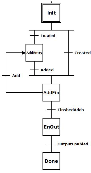 To the right is a stage diagram
of a stage that will all the adding of any number of entries to either
an existing PLS table or a newly created one.
To the right is a stage diagram
of a stage that will all the adding of any number of entries to either
an existing PLS table or a newly created one. To the right is the ladder equivalent of the above
stage diagram that uses the CTPLSADD instruction to create and/or add
any number of entries to either a pre-existing PLS table or a newly created
one.
To the right is the ladder equivalent of the above
stage diagram that uses the CTPLSADD instruction to create and/or add
any number of entries to either a pre-existing PLS table or a newly created
one.