Topic: DMD0252
Module Configuration
Some Intelligent I/O modules must be preconfigured before they can be used in a Do-more Designer project - for example a CTRIO modules must be configured within the System Configuration, and an ERMs must be configured with ERM Workbench, etc. Before these modules can be used in a project, Do-more Designer needs to know how the modules are configured. This information is stored in a Module Configuration.
A module configuration consists of a Name that will referenced by instructions that can use the module, a Type that defines the type of module configuration that is required to access the module, and a Location that specifies the base and slot where the module physically resides. The module's configuration creates a logical connection between the Do-more Designer project and the I/O module, thereby eliminating the need to use the physical Base & Slot addressing in the project.
At power-up, the Do-more controller will create a default module configuration for each Intelligent I/O module that requires one. The default Name for each of the configurations will be in the form <Type>_<Slot Number>, for example, a CTRIO module in slot 2 will have a default configuration called CTRIO_002. Because the modules have very different configuration, there is a type-specific editor for each type of module.
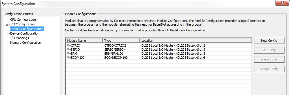
Module Name - this column displays the logical name assigned to the I/O module.
Type - this column displays the type of I/O module configuration used for the module in that Location
CTRIO/CTRIO2 - if the configuration is for a CTRIO or CTRIO2 module
ECOM/ECOM100 - if the configuration is for an ECOM or ECOM100 module
ERM/ERM100 - if the configuration is for an ERM or ERM100 module
SERIO/SERIO4 - if the configuration is for a SERIO or SERIO-4 module
Location - this column displays the I/O Master, the Base and the Slot number of the I/O module. If a module configuration exists for a module that is not currently in the base the location will change to Disconnected.
 Creating and Editing Module
Configurations:
Creating and Editing Module
Configurations:
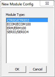
New Config - is used to create a new module configuration. Clicking the New Config button will display the following dialog:
Select the Module Type from the list that matches the I/O Module to add
CTRIO/CTRIO2 - to add a module configuration for a CTRIO or CTRIO2
ECOM/ECOM100 - to add a module configuration for an ECOM or ECOM100
ERM/ERM100 - to add a module configuration for an ERM or ERM100
SERIO/SERIO-4 - to add a module configuration for a SERIO or SERIO-4
An empty module configuration will be created and the Edit Config dialog for the Module Type will be automatically opened.
Edit Config - will open a type-specific editor to change an existing module configuration. Refer to the following Edit dialogs for the information required by the individual Module Types.
Edit the Configuration for a CTRIO Module
This dialog facilitates the configuration of the CTRIO/CTRIO2 module for use in the Do-more controller CTRIO instructions.
Before the advent of Do-more Designer software, configuration of the CTRIO module was done by a free utility called CTRIO Workbench which could optionally store the CTRIO's configuration into a .CWB file. That utility is not needed with Do-more Designer. However, the dialog here will allow the import of previously stored .CWB files created by CTRIO Workbench. It will also allow the export of any CTRIO configuration done here to be exported to a CTRIO-Workbench-compatible .CWB file.
Another important feature of this configuration dialog is that it doesn't matter what configuration is stored in the CTRIO/CTRIO2 module themselves; whether they are freshly out-of-the-box or have previously stored configurations from CTRIO Workbench. Whatever configuration exists in the CTRIO/CTRIO2 module, it will be overwritten by the configuration in this dialog. This dialog does not write the CTRIO configuration to the CTRIO's ROM, but only its RAM. This is because the CTRIO's configuration is now stored as a permanent part of the Do-more controller's System Configuration.
After configuring the module the Name fields will have default names. These can optionally be given meaningful and unique names for each of the configured resources. The names will be used to automatically create Do-more Devices that will be available to the CTRIO instructions.
Module Configuration Name -
This name will become a Do-more Device
so be careful to choose a meaningful and unique name. Module names follow
Nickname rules
Info - Not an editable field, but gives information read directly from the CTRIO module.
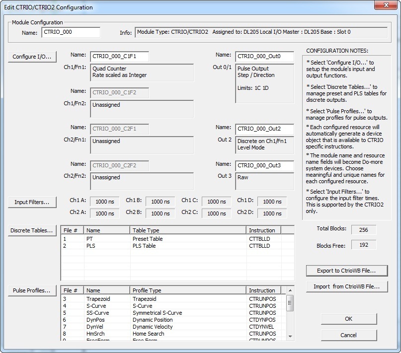
To configure the CTRIO, make sure the CONFIGURATION NOTES are read and followed.
Total Blocks - The total number of memory blocks allocated for Discrete Tables and Pulse Profiles. The number of memory blocks used varies between Pulse Profiles and Discrete Tables.
Blocks Free - The total number of memory blocks not being used.
Export to CtrioWB File... (button): Once a satisfactory configuration is complete, pressing this button allows the exporting of this configuration to a classic CTRIO Workbench .CWB file.
Import from CtrioWB File... (button): Pressing this button allows the importing from a previously stored CTRIO-Workbench-compatible .CWB file.
Configure I/O... (button): Pressing this button pulls up the setup dialogs for configuring the CTRIO's input and output functions. To the right of this button the current configuration of the CTRIO module along with the default names is shown. Click here for help on Configure I/O.
Input Filters... (button): (CTRIO2 only) Pressing this button pulls up the setup dialog for configurating the input filter times. To the right of this button the current values for these filters are shown in for each CTRIO input in nanoseconds. Click here for help on Input Filters.
Discrete Tables... (button): Pressing this button pulls up the setup dialogs for configuring preset tables (CTRIO/CTRIO2) and PLS tables (CTRIO2 only) for CTRIO discrete outputs. Click here for help on Discrete Tables.
File # - Automatically assigned number when the Discrete Table was created.
Name - Optional name chosen during configuration.
Table Type - Type of Discrete Table configured
Preset Table - A list of presets similar to an event drum that allow the control of a CTRIO discrete output based on a counter or timer input function
PLS Table - Programmable Limit Switch. A list of presets that allow the control of a CTRIO discrete output based on a counter or timer input function
Instruction - Shows the Do-more instruction associated with this type of Discrete Table.
Pulse Profiles... (button): Pressing this button pulls up the setup dialogs for configuring profiles for CTRIO pulse outputs. Click here for help on Pulse Profiles.
File # - Automatically assigned number when the Pulse Profile was created.
Name - Optional name chosen during configuration.
Profile Type - Type of Pulse Profile configured.
Trapezoid - asymmetrical linear trapezoidal movement to a total number of pulses
S-Curve - S-shaped movement to a total number of pulses
Symmetrical S-Curve - symmetrical S-shaped movement to a total number of pulses
Dynamic Position - symmetrical linear trapezoidal movement where any number of positions can be specified on-the-fly
Dynamic Velocity - asymmetrical linear trapezoidal movement where any number of velocities can be specified on-the-fly
Home Search - movement profile used to find a home position utilizing a CTRIO2 input
Free Form - custom movement profile allowing any number of steps each having a number of pulses to be output at a specified frequency
Dynamic Position Plus - (CTRIO2 only) asymmetrical linear trapezoidal movement where any number of positions can be specified on-the-fly with the additional option of using a quadrature encoder attached to the CTRIO2 input channel to provide the position
Trapezoid Plus - (CTRIO2 only) asymmetrical linear trapezoidal movement to a run-time-provided position with the additional option of using a quadrature encoder attached to the CTRIO2 input channel to provide the position
Trapezoid w/Limits - (CTRIO2 only) asymmetrical linear trapezoidal movement to a deceleration trigger (a CTRIO2 input) and then to a stop trigger (a position or a CTRIO2 input) with the additional option of using a quadrature encoder attached to the CTRIO2 input channel to provide the position.
Instruction - Shows the Do-more instruction associated with this type of pulse profile
Edit the Configuration for a SERIO Module
Module Configuration Name -
The Module Configuration Name will become a Do-more
Device, be careful to choose a meaningful and unique name. Module
names follow Nickname rules
Port A / B / C Name - The port Name will become a Do-more Device, be careful to choose a meaningful and unique name.
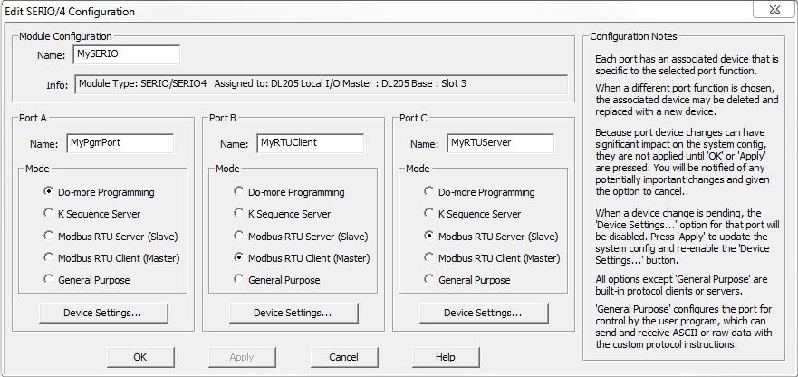
Mode - designates the functional mode for each of the serial ports on the SERIO/4 module.
Because each mode has an associated device that is specific to that mode, changing the mode will cause the underlying device to be deleted and/or created as needed. Because the port device changes can have a significant impact on the System Configuration, they are not committed until the 'OK' or Apply' buttons are clicked by the programmer.
After selecting the Mode for a port, click the Apply button to commit that selection. At that point the programmer can click the Device Settings... button for that port to configure the Baud Rate, Parity, Station Address, etc., for that individual port.
 Do-more
Programming - select this option to setup the port to work with
Do-more Designer programming software.
Do-more
Programming - select this option to setup the port to work with
Do-more Designer programming software.
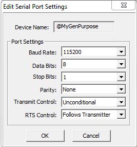
Device Name - displays the logical name of the serial port Device
Port Settings
- set the serial port configuration
Baud Rate
115200, 57600, 38400, 19200, 9600, 4800, 2400, 1200, 300
Data Bits
7, 8
Stop Bits
1, 2
Parity
None, Odd, Even
Transmit Control - designates when data will be transmitted
Unconditional - data will be transmitted as soon as it reaches the output buffer
Wait for CTS - data will be transmitted when the CTS line is asserted
Delayed 5ms, Delayed 50ms, Delayed 250ms, Delayed 500ms - after data reaches the output buffer, the RTS line will be asserted, and the transmitting of the data will be delayed by the selected number of milliseconds.
RTS Control - selects how the RTS line will operate
Follows Transmitter -
Manual - allows programmatic control of the RTS line through the struct member IntSerial.RTS.
Off - forces the RTS line to always be OFF
On - forces the RTS line to always be ON
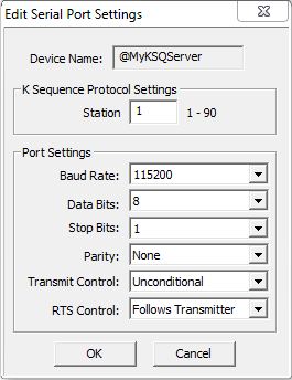 K
Sequence Server - select this option to have the port respond to
client devices running K-Sequence protocol.
K
Sequence Server - select this option to have the port respond to
client devices running K-Sequence protocol.
Device Name - displays the logical name of the serial port Device
K Sequence Protocol Settings
- configuration settings used when this Device responds to K-Sequence
Client requests:
Station - designates the ID of the K-Sequence Server Device, this can be any constant from 1 to 90.
Port Settings
Baud Rate
115200, 57600, 38400, 19200, 9600, 4800, 2400, 1200, 300
Data Bits
7, 8
Stop Bits
1, 2
Parity
None, Odd, Even
Transmit Control - designates when data will be transmitted
Unconditional - data will be transmitted as soon as it reaches the output buffer
Wait for CTS - data will be transmitted when the CTS line is asserted
Delayed 5ms, Delayed 50ms, Delayed 250ms, Delayed 500ms - after data reaches the output buffer, the RTS line will be asserted, and the transmitting of the data will be delayed by the selected number of milliseconds.
RTS Control - selects how the RTS line will operate
Follows Transmitter -
Manual - allows programmatic control of the RTS line through the struct member IntSerial.RTS.
Off - forces the RTS line to always be OFF
On - forces the RTS line to always be ON
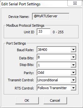 Modbus
RTU Server (Slave) - select this option to have the port respond
to client devices running Modbus/RTU protocol.
Modbus
RTU Server (Slave) - select this option to have the port respond
to client devices running Modbus/RTU protocol.
Device Name - displays the logical name of the serial port Device
Modbus Protocol Settings - configuration
settings used when this Device responds to Modbus RTU Client requests:
Unit ID - designates the Unit ID of the Modbus RTU Server Device, this can be any constant from 0 to 255.
Port Settings
Baud Rate
115200, 57600, 38400, 19200, 9600, 4800, 2400, 1200, 300
Data Bits
7, 8
Stop Bits
1, 2
Parity
None, Odd, Even
Transmit Control - designates when data will be transmitted
Unconditional - data will be transmitted as soon as it reaches the output buffer
Wait for CTS - data will be transmitted when the CTS line is asserted
Delayed 5ms, Delayed 50ms, Delayed 250ms, Delayed 500ms - after data reaches the output buffer, the RTS line will be asserted, and the transmitting of the data will be delayed by the selected number of milliseconds.
RTS Control - selects how the RTS line will operate
Follows Transmitter -
Manual - allows programmatic control of the RTS line through the struct member IntSerial.RTS.
Off - forces the RTS line to always be OFF
On - forces the RTS line to always be ON
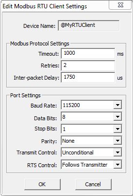 Modbus
RTU Client (Master) - select this option to make the port available
for use by the Do-more controller's
Modbus Network
Read (MRX) and Modbus
Network Write (MWX) instructions.
Modbus
RTU Client (Master) - select this option to make the port available
for use by the Do-more controller's
Modbus Network
Read (MRX) and Modbus
Network Write (MWX) instructions.
Device Name - displays the logical name of the serial port Device
Modbus Protocol Settings - configuration settings used when this Device is used in a Modbus Network Read (MRX) or Modbus Network Write (MWX) instruction:
Timeout - how many milliseconds should the instruction wait for the remote Modbus RTU Server to respond, this can be any constant from 0 to 32767.
Retries - how many times should the instruction retry the communication with the remote Modbus RTU Server, this can be any constant from 0 to 255.
Inter-packet Delay - the amount of time (in microseconds) that will be placed between the Modbus RTU packets as they are sent. This can be any be any constant between 0 and 65535. The inter-packet delay creates the required "dead time" on the wire that Modbus uses to frame a packet. The Modbus specification requires this value to be a minimum of 3.5 characters times (based on baud rate). If the value entered is smaller than the required time, the Modbus RTU Client will use the minimum required time instead of the value that is entered. If the value entered is larger than the required time, the value entered will be used.
Use this formula to calculate the inter-packet delay (in microseconds) based on baud rate:
( 3.5 * (number of bits in a character / baud rate) ) * 1,000,000
For example: using a 10-bit character (1 start bit, 8 data bits, no parity bit, and 1 stop bit) at 19200 baud:
( 3.5 ( 10 / 19200 ) ) * 1,000,000 = 1823 microseconds
Port Settings
Baud Rate
115200, 57600, 38400, 19200, 9600, 4800, 2400, 1200, 300
Data Bits
7, 8
Stop Bits
1, 2
Parity
None, Odd, Even
Transmit Control - designates when data will be transmitted
Unconditional - data will be transmitted as soon as it reaches the output buffer
Wait for CTS - data will be transmitted when the CTS line is asserted
Delayed 5ms, Delayed 50ms, Delayed 250ms, Delayed 500ms - after data reaches the output buffer, the RTS line will be asserted, and the transmitting of the data will be delayed by the selected number of milliseconds.
RTS Control - selects how the RTS line will operate
Follows Transmitter -
Manual - allows programmatic control of the RTS line through the struct member IntSerial.RTS.
Off - forces the RTS line to always be OFF
On - forces the RTS line to always be ON
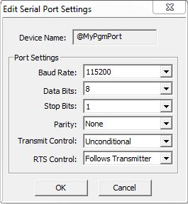
 General
Purpose - select this option to make the port available for use
by the Do-more controller's Stream
in Data from Device (STREAMIN) and Stream
Out Data to Device (STREAMOUT) instructions.
General
Purpose - select this option to make the port available for use
by the Do-more controller's Stream
in Data from Device (STREAMIN) and Stream
Out Data to Device (STREAMOUT) instructions.
Device Name - displays the logical name of the serial port Device
Port Settings
Baud Rate
115200, 57600, 38400, 19200, 9600, 4800, 2400, 1200, 300
Data Bits
7, 8
Stop Bits
1, 2
Parity
None, Odd, Even
Transmit Control - designates when data will be transmitted
Unconditional - data will be transmitted as soon as it reaches the output buffer
Wait for CTS - data will be transmitted when the CTS line is asserted
Delayed 5ms, Delayed 50ms, Delayed 250ms, Delayed 500ms - after data reaches the output buffer, the RTS line will be asserted, and the transmitting of the data will be delayed by the selected number of milliseconds.
RTS Control - selects how the RTS line will operate
Follows Transmitter -
Manual - allows programmatic control of the RTS line through the struct member IntSerial.RTS.
Off - forces the RTS line to always be OFF
On - forces the RTS line to always be ON
 Edit
ERM or ERM100 Configuration:
Edit
ERM or ERM100 Configuration:
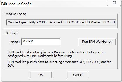
ERM (Ethernet Remote Master) modules are DL205 modules that provide Ethernet connectivity to I/O in remote bases. The ERM modules do not require additional configuration within Do-more Designer, but they must be configured with ERM Workbench before they can operate correctly.
ERM modules are treated as legacy modules, meaning the ERM will place the I/O data read from the remote bases into DLX, DLY, DLC, and DLV memory in the Do-more controller, and data to be sent to the remote bases will be read from the same memory blocks.
Name - The ERM Name will become
a Device, be careful to choose a meaningful and unique name. The ERM name
must follow Nickname rules
Run ERM Workbench - click to launch the ERM Workbench utility
Edit ECOM or ECOM100 Configuration:
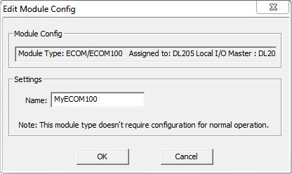 Name - The ECOM Name
will become a Device, be careful to choose a meaningful and unique name.
ECOM module configuration Names follow Nickname
rules
Name - The ECOM Name
will become a Device, be careful to choose a meaningful and unique name.
ECOM module configuration Names follow Nickname
rules
Note: the ECOM and ECOM100 modules are configured with NetEdit and do not require additional configuration within Do-more Designer to operate normally.
Handling Disconnected Module Configurations:
When a Do-more controller is powered up, it looks through the System Configuration for Module Configurations. Then, for each Module Configuration that is found, it checks to see if the correct I/O module is still installed in the correct location. Disconnected module configurations appear for any slot that has a module configuration but the I/O module itself is missing or is not the correct module type for that configuration.
Note: the 'Module configuration changed at power up (ST134)' Info message will be generated and displayed in the System Information dialog, and 'Info' will be displayed on the Status Bar.
The screen capture shows a disconnected CTRIO module configuration.
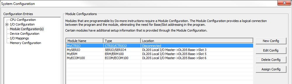
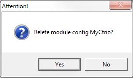
Delete Config - is used to delete a disconnected module configuration. Highlight the disconnected configuration in the list and click the Delete button, confirm the delete operation on the subsequent dialog.
Assign Config - is used to connect a Disconnected module configuration to the I/O module in a designated location. Highlight the disconnected configuration in the list and click the Assign Config button. The Assign Module Config dialog will display a list of the I/O modules in locations that can be assigned to the selected module configuration. Highlight the I/O module in the list to use.
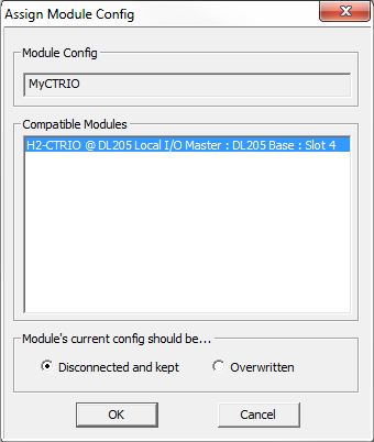
Module's current config should be ... - this option designates what to do with the module configuration of the target I/O module
Disconnected and Kept - the target I/O module's existing module configuration data will be saved and marked as Disconnected before the new module configuration is assigned
Overwritten - the target I/O module's module configuration will be overwritten when the new module configuration is assigned
Click OK to Assign the selected I/O module to the Module Configuration, then click Yes on the subsequent confirmation dialog to complete the operation.
Click Cancel to leave the current module configuration intact.
See Also:
Module Configuration