Topic: DMD0250
I/O Mappings
At power-up, Do-more controllers will automatically detect any installed I/O modules (including specialty modules) and create the correct I/O configuration and assign I/O addresses for them. For most applications, you will never have to change the configuration. I/O addresses are assigned in decimal, starting at X0 and Y0 for Discrete I/O and WX0 and WY0 for Analog I/O, beginning in the slot adjacent to the Do-more CPU. The addresses are assigned in increments of 8, depending on the number of points for the I/O module. Discrete and Analog modules can be mixed in any order, but there may be restrictions placed on some specialty modules.
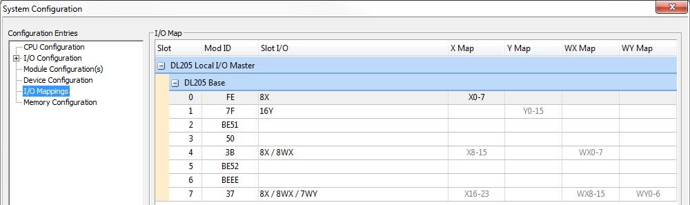
The I/O Map group displays the current mapping for the I/O modules in the system, and allows the user to manually assign the I/O mapping for any of the I/O modules in the system.
Slot - this column displays the slot number in which the module is detected
Mod ID - this column displays the Module ID of the I/O module that is detected.
Note: I/O modules that have the same I/O footprint will also have the same Module ID regardless of the type of I/O, for example, all of the 8-point Discrete input modules will have the same Module ID, regardless of whether they have AC or DC inputs.
Slot I/O - this column displays
the number and type of I/O points that the detected I/O module consumes.
Modules that have multiple types of I/O will display each number and type
separated by a "/":
X - Discrete Inputs - for example 16X = 16 Discrete Inputs
Y - Discrete Outputs - for example 8Y = 8 Discrete Outputs
Note: 12pt. Discrete I/O modules consume 16 points. The first 6 points are assigned, two are skipped, and then the next 6 points are assigned. For example, a D2-12TA installed in slot 0 would use Y0 to Y5, and Y8 toY13 for the actual inputs; Y6 to Y7 and Y14 to Y15 would be unused.
Note: 4pt. Discrete I/O modules consume 8 points. The first 4 points are assigned to the actual I/O points, the next 4 are unused. For example, a D2-04TD1 installed in slot 0 would use X0 to X3 for the actual inputs and X4 to X7 would be unused.
WX - Word (Analog) Inputs (16-bit signed) - for example 4X / 4WX = 4 Discrete Inputs and 4 Word (Analog) Inputs
Note: the Discrete Inputs for Analog Input modules are the 'broken transmitter' bits, one bit per channel
WY - Word (Analog) Outputs (16-bit signed) - for example 4WY = 4 Word (Analog) Outputs
X Map - this column displays the current I/O Addressing assignment for the Discrete Input module in that slot
Y Map - this column displays the current I/O Addressing assignment for the Discrete Output module in that slot
WX Map - this column displays the current I/O Addressing assignment for the Word (Analog) Input module in that slot
WY Map - this column displays the current I/O Addressing assignment for the Word (Analog) Output module in that slot
How to Manually Configure the I/O Map
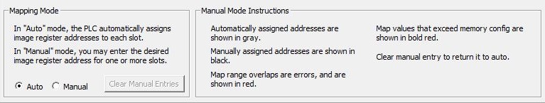
Auto - (the default) in Auto mode the Do-more controller automatically assigns I/O addresses to the modules in each slot. Automatically assigned I/O addresses are displayed in gray.
Manual - It may never become necessary, but controllers allow manual I/O address assignments for any of the I/O modules in the system. You can manually modify an automatic configuration to match arbitrary I/O numbering. After selecting Manual Mode, left-click with the mouse on any of the current I/O address blocks in the I/O Map grid to change the current I/O Map value. Only the beginning I/O address for a module can be specified, the range of addresses will be automatically assigned based on the number of I/O points the module consumes. Manually assigned I/O addresses will be displayed in black.
WARNING: If you manually configure an I/O slot, the I/O addressing for the other modules may change. This is because the controller does not allow duplicate I/O addresses. Any I/O configuration errors must be corrected before you place the controller in RUN mode. Uncorrected errors can cause unpredictable machine operation that can result in a risk of personal injury or damage to equipment.
Note: Manually assigned addresses that create overlapping ranges will be displayed in red and must be corrected before the changes can be saved.
Note: Manually assigned addresses that result in ranges outside of the configured range of that I/O Type will be displayed in bold red and must be corrected before the changes can be saved.
Clear Manual Entries - (only valid in Manual Mode) - click this button to remove any manual changes that have been applied and revert to the Automatically assigned addresses for each I/O module in the system.
See Also:
I/O Mappings