Topic: DMD0248
Device Configuration
Devices are pre-configured interfaces that provide programmatic access to system resources. Additional user configuration of the devices, for example baud rates for serial ports, is provided for in this dialog. Some devices are automatically created - for example @UserLog and @DMLogger - and although they are listed here, they cannot be deleted or edited.
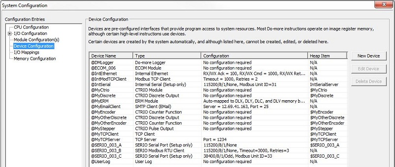
Device Name - this column displays the current name of the device, it is this name that is referenced in the instructions that target the Device.
Type - this column displays the driver type used for the Device. '(Setup only)' is used to denote Devices that are data servers, that is, they are NOT used as target device in instructions.
Configuration - this column displays the current configuration for the Device. 'No configuration required' is used to denote Devices that have a fixed configuration.
Heap Item - this column displays the Heap Item that is used for programmatic access to the Device.
Add a New Device
The three buttons at the right allow the programmer to modify the current
system Configuration by adding, or deleting, or editing Device configurations.
Click the New Device button to
invoke the Add Device dialog to create one of the following Devices:
Modbus TCP Client - defines a connection to a Modbus TCP/IP Server, and is available only if the controller has an onboard Ethernet port. Modbus TCP Client devices are used by the Modbus Network Read (MRX) and Modbus Network Write (MWX) instructions.
Note: If the project will be using Modbus Read (MRX) instructions to read data from multiple Modbus TCP Servers, the best performance will be had by creating a separate Modbus TCP Client device for each of the Modbus Servers.
SMTP Client (Email) - defines a connection to an Email Server, and is available only if the controller has an onboard Ethernet port. SMTP Client Devices are used by the Send Email (EMAIL) instruction to specify the target SMTP Server, SMTP port number, and user authentication.
TCP Client - defines a client-side TCP socket for general purpose TCP/IP networking, useful in cases where the controller needs to send or receive data through a custom streaming protocol. TCP Client devices are only available if the controller has an onboard Ethernet port. Connections to TCP Servers are created through the Open TCP Connection (OPENTCP) instruction.
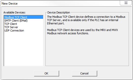
TCP Server - defines a server-side TCP socket for general purpose TCP/IP networking, useful in cases where the controller needs to send or receive data through a custom streaming protocol. TCP Server devices are only available if the controller has an onboard Ethernet port. The TCP Server is managed through the Start Listening on TCP Port (TCPLISTEN) instruction.
UDP Connection - defines a UDP socket for general purpose TCP/IP networking, useful in cases where the controller needs to send or receive data through a custom streaming protocol. UDP Connection devices are only available if the controller has an onboard Ethernet port. UDP Connection devices are used by used by the Input UDP Packet to String (UDPIN) and Output UDP Packet from String (UDPOUT) instructions.
Click the Edit Device button to open the edit dialog for the currently highlighted Device.
Click the Delete Device to open deletes the currently highlighted Device.
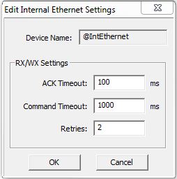
Onboard Ethernet Port (@IntEthernet)
Device Name - the logical name assigned to the Internal Ethernet Device
RX/WX Settings - configuration
settings used when this Device is used in a DirectLOGIC
Read Network (DLRX) or a DirectLOGIC
Read Network (DLWX) instruction:
ACK Timeout - how many milliseconds should the instruction wait for an ACK from the remote DirectLOGIC PLC, this can be any constant from 0 to 32767.
Command Timeout - how many milliseconds should the instruction wait for the remote DirectLOGIC PLC to respond to a data request, this can be any constant from 0 to 32767.
Retries - how many times should the instruction retry the communication with the remote DirectLOGIC PLC, this can be any constant from 0 to 255.
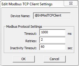
Internal Modbus TCP Client (@IntModbusTCPClient)
Device Name - the logical name assigned to the Modbus TCP Client Device
Modbus Protocol Settings - configuration
settings used when this Device is used in a Modbus
Network Read (MRX) or Modbus
Network Write (MWX) instruction:
Timeout - how many milliseconds should the instruction wait for the remote Modbus TCP Server to respond, this can be any constant from 0 to 32767.
Retries - how many times should the instruction retry the communication with the remote Modbus TCP Server, this can be any constant from 0 to 255.
Inactivity Timeout - how many seconds after the last communication from the remote Modbus TCP Server to wait before the controller terminates the connection, this can be any constant from 15 to 3600.
Onboard Serial Port (@IntSerial) and H2-SERIO or H2-SERIO-4 Module
All of the Serial Port Devices in a controller have a common Port Settings section with the following configuration options:
Device Name - displays the logical name of the serial port Device
Port Settings
Baud Rate
115200, 57600, 38400, 19200, 9600, 4800, 2400, 1200, 300
Data Bits
7, 8
Stop Bits
1, 2
Parity
None, Odd, Even
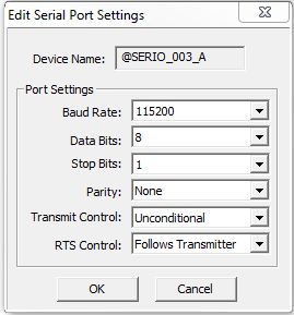
Transmit Control - designates when data will be transmitted
Unconditional - data will be transmitted as soon as it reaches the output buffer
Wait for CTS - data will be transmitted when the CTS line is asserted
Delayed 5ms, Delayed 50ms, Delayed 250ms, Delayed 500ms - after data reaches the output buffer, the RTS line will be asserted, and the transmitting of the data will be delayed by the selected number of milliseconds.
RTS Control - selects how the RTS line will operate
Follows Transmitter -
Manual - allows programmatic control of the RTS line through the struct member IntSerial.RTS.
Off - forces the RTS line to always be OFF
On - forces the RTS line to always be ON
Serial Port as KSequence Server
When the module configuration designates the Onboard Serial Port or a port on the H2-SERIO or H2-SERIO-4 as a K Sequence Server, the additional Device configuration option is available:
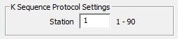
K Sequence Protocol Settings
- configuration settings used when this Device responds to K Sequence
Client requests:
Station - designates the ID of the K Sequence Server Device, this can be any constant from 1 to 90.
Serial Port as Modbus RTU Client
When the module configuration designates the Onboard Serial Port or a port on the H2-SERIO or H2-SERIO-4 as a Modbus RTU Client, the additional Device configuration options are available:
Modbus Protocol Settings - configuration
settings used when this Device is used in a Modbus
Network Read (MRX) or Modbus
Network Write (MWX) instruction:
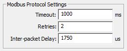
Timeout - how many milliseconds should the instruction wait for the remote Modbus RTU Server to respond, this can be any constant from 0 to 32767.
Retries - how many times should the instruction retry the communication with the remote Modbus RTU Server, this can be any constant from 0 to 255.
Inter-packet Delay - the amount of time (in microseconds) to place between the Modbus/TCP packets as they are sent, this can be any be any constant value between 0 and 65535.
Serial Port as Modbus RTU Server
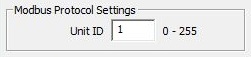
When the module configuration designates the Onboard Serial Port or a port on the H2-SERIO or H2-SERIO-4 as a Modbus RTU Server, the additional Device configuration option is available:
Modbus Protocol Settings - configuration
settings used when this Device responds to Modbus RTU Client requests:
Unit ID - designates the Unit ID of the Modbus RTU Server Device, this can be any constant from 0 to 255.
SMTP Client Device (@IntEthernet)
The Edit SMTP Client Settings dialog is used to create an SMTP connection from the Do-more controller to an SMTP server in order for the controller to send Email. The information that is required to configure an SMTP connection is always going to be specific to the installation. It is up to the programmer to locate the required information.

Device Name - the name to give
the SMTP Client. This is the name that will be referenced in the Send
Email (EMAIL) instructions. Device Names can consists of 1 to 16 alphanumeric
characters. Device names must follow Nickname
rules
SMTP Server IP Address - the
IP address of the SMTP server that will process the Email sent from the
controller. The controller does not have the DNS capability, that is,
it cannot use the name of the SMTP server to lookup the SMTP server's
IP Address.
DNS Loopkup - invokes the IP Address Lookup utility that can find the
IP Address for a given SMTP Server name.
SMTP Server Port - the default value of 25 is the standard IP port number that is used by SMTP servers. This normally should not need to be changed.
Timeout - this is the amount of time (in seconds) the SMTP Client will attempt to connect to the specified SMTP server before reporting an error. The default value of 30 seconds should be sufficient in most instances. Be aware that it is quite normal for communications with SMTP servers to take several seconds of time; setting this value too low will only cause needless problems.
'From' Email Address - specifies the Email address that all Emails using this SMTP Client will use in the 'From' field. Email addresses must be in the form of X@Y.Z. SMTP servers typically require that the 'From' address be configured as a recipient address on that SMTP server before they will accept Emails from that address.
Authentication - if the SMTP server requires authentication before it will accept an Email from the controller, select one of the following three methods:
Disabled - if the SMTP server does not require authentication
AUTH LOGIN - Authenticate by logging into the SMTP Server with the Username and Password specified below
AUTH PLAIN - Authenticate by logging into the SMTP Server with the Username and Password specified below
POP before SMTP - an authentication that attempts to get Email before attempting to send an Email, the premise being that if an Email client can login and read Email the Client must be legitimate
Port Number - the default port number of 110 is the standard IP port number for POP3 requests and should not need to be changed
Account Information - these three authentication methods require a UserID and Password. For 'AUTH LOGIN' and 'AUTH PLAIN', the account information is for the SMTP account, for the 'POP before SMTP' method, the account information is for the POP3 account.
Username - 1 to 64 characters
Password - 1 to 19 characters
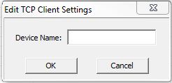
TCP Client Device
Defines a client-side TCP socket for general purpose TCP/IP networking, which is useful in cases where the Do-more controller needs to send or receive data through a custom streaming protocol. TCP Client devices are only available if the Do-more controller has an onboard Ethernet port.
TCP Client devices require no configuration, they can create connections to TCP Server devices, but cannot accept connections from other TCP clients.
Connections to TCP Servers are created through the Open TCP Connection (OPENTCP) instruction.
Note: the TCP Client device is NOT the correct choice for connecting to device that are using Modbus/TCP protocol, use the Modbus/TCP Client device as described above.
Device Name - the name to give
the TCP Client. This is the name that will be referenced in the OPENTCP
instruction. Device Names can consists of 1 to 16 alphanumeric characters.
Device names must follow Nickname
rules
TCP Server Device
Defines a server-side TCP socket for general purpose TCP/IP networking, which is useful in cases where the Do-more controller needs to send or receive data through a custom streaming protocol. TCP Server devices are only available if the Do-more controller has an onboard Ethernet port.
TCP Server devices are configured with a local port number, which defines the 'listening' port. TCP Server devices can accept connections from a single TCP Client, and upon accepting the client connection, will invoke a Program code-block specified for the 'connected' state, and a different Program code-block when the TCP connection is lost.
The TCP Server is managed through the Start
Listening on TCP Port (TCPLISTEN) instruction.
Note: the TCP Server device is NOT the correct choice for allowing a connection from an external device that is using Modbus/TCP protocol, use the built-n Modbus/TCP Server.
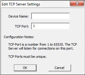
Device - the name to give the
SMTP Client. This is the name that will be referenced in the Send Email
(EMAIL) instructions. Device Names can consists of 1 to 16 alphanumeric
characters. Device names must follow Nickname
rules
UDP Port - the port number to list on. This can be any decimal constant in the range of 1 to 65535
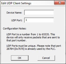
UDP Connection Device
Defines a UDP socket for general purpose TCP/IP networking, useful in cases where the controller needs to send or receive data through a custom streaming protocol. UDP Connection devices are only available if the controller has an onboard Ethernet port.
UDP Connection devices are used by the Input Data from Packet Device (PACKETIN) and
Output UDP to Packet Device (PACKETOUT) instructions.
Device Name - the name to give
the UDP Connection. This is the name that will be referenced in the PACKETIN
and PACKETOUT instructions. Device Names can consists of 1 to 16 alphanumeric
characters. Device names must follow Nickname
rules
UDP Port - the port number to use for this connection. This can be any decimal constant in the range of 1 to 65535. Each UDP connection must have a unique port number.
Note: port number 28784 is already used by the Do-more controller.
See Also:
Device Configuration