Topic: DMD0247
CPU Configuration
This page of the System Configuration dialog provides the selections necessary to configure the onboard hardware of the Do-more controller.
 Serial
Port Mode
Serial
Port Mode
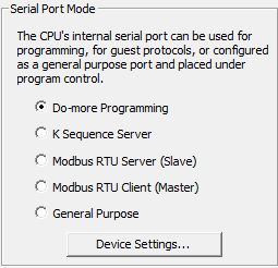
The Serial Port Mode configuration selects the operational mode for the onboard serial port of the controller. The selections are mutually exclusive, meaning that the onboard serial port can only operate in one of the following modes at any given time.
Do-more Programming - select this option to make the serial port operate as a programming port for the Do-more Designer programming software.
After selecting this option, click the Device Settings button to change the onboard serial port's hardware configuration as follows:
Port Settings
Baud Rate
115200, 57600, 38400, 19200, 9600, 4800, 2400, 1200, 300
Data Bits
7, 8
Stop Bits
1, 2
Parity
None, Odd, Even
Transmit Control - designates when data will be transmitted
Unconditional - data will be transmitted as soon as it reaches the output buffer
Wait for CTS - data will be transmitted when the CTS line is asserted
Delayed 5ms, Delayed 50ms, Delayed 250ms, Delayed 500ms - after data reaches the output buffer, the RTS line will be asserted, and the transmitting of the data will be delayed by the selected number of milliseconds.
RTS Control - selects how the RTS line will operate
Follows Transmitter -
Manual - allows programmatic control of the RTS line through the struct member IntSerial.RTS.
Off - forces the RTS line to always be OFF
On - forces the RTS line to always be ON
KSequence
Server - select this option to connect a third-party device that
communicates via KSequence protocol. KSequence is a proprietary protocol
used by AutomationDirect (Koyo) hardware.
Devices that connect with the KSequence protocol will only have access
to the following blocks of memory in the controller (the ranges are numbered
in octal):
DLX: Inputs, the default range is DLX0 - DLX777
DLY: Outputs, the default range is DLY0 - DLY777
DLC: Control Relays: the default range is DLC0 - DLC777
DLV: V-Memory: the default range is DLV0 - DLV3777
Note: The size of the memory blocks available to the KSequence driver can be changed in the controller's Memory Configuration.
After selecting this option, click the Device Settings button to change the onboard serial port's hardware configuration as follows:
K Sequence
Protocol Settings - configuration settings used when this Device
responds to K-Sequence Client requests:
Station - designates the ID of the K-Sequence Server Device, this can be any constant from 1 to 90.
Port Settings
Baud Rate
115200, 57600, 38400, 19200, 9600, 4800, 2400, 1200, 300
Data Bits
7, 8
Stop Bits
1, 2
Parity
None, Odd, Even
Transmit Control - designates when data will be transmitted
Unconditional - data will be transmitted as soon as it reaches the output buffer
Wait for CTS - data will be transmitted when the CTS line is asserted
Delayed 5ms, Delayed 50ms, Delayed 250ms, Delayed 500ms - after data reaches the output buffer, the RTS line will be asserted, and the transmitting of the data will be delayed by the selected number of milliseconds.
RTS Control - selects how the RTS line will operate
Follows Transmitter -
Manual - allows programmatic control of the RTS line through the struct member IntSerial.RTS.
Off - forces the RTS line to always be OFF
On - forces the RTS line to always be ON
Modbus RTU
Server (Slave) - select this option to allow a third-party device
that communicates via Modbus RTU protocol to connect to the serial port.
Devices that connect with the Modbus/RTU protocol will only have access
to the following blocks on memory in the controller (the ranges are numbered
in decimal):
MI: Inputs, the default range is MI0 - MI1023
MC: Outputs, the default range is MC0 - MC1023
MIR: Input Registers: the default range is MIR0 - MIR2047
MHR: Holding Registers: the default range is MHR0 - MHR2047
Note: The size of the memory blocks available to the Modbus/RTU driver can be changed in the controller's Memory Configuration.
After selecting this option, click the Device Settings button to change the onboard serial port's hardware configuration as follows:
Modbus Protocol
Settings - configuration settings used when this Device responds
to Modbus RTU Client requests:
Unit ID - designates the Unit ID of the Modbus RTU Server Device, this can be any constant from 0 to 255.
Port Settings
Baud Rate
115200, 57600, 38400, 19200, 9600, 4800, 2400, 1200, 300
Data Bits
7, 8
Stop Bits
1, 2
Parity
None, Odd, Even
Transmit Control - designates when data will be transmitted
Unconditional - data will be transmitted as soon as it reaches the output buffer
Wait for CTS - data will be transmitted when the CTS line is asserted
Delayed 5ms, Delayed 50ms, Delayed 250ms, Delayed 500ms - after data reaches the output buffer, the RTS line will be asserted, and the transmitting of the data will be delayed by the selected number of milliseconds.
RTS Control - selects how the RTS line will operate
Follows Transmitter -
Manual - allows programmatic control of the RTS line through the struct member IntSerial.RTS.
Off - forces the RTS line to always be OFF
On - forces the RTS line to always be ON
Modbus RTU Client (Master) - select this option to allow the onboard serial port to be used by the Modbus Network Read (MRX) and Modbus Network Write (MWX) instructions. Once enabled, the MRX and MWX instructions will have the option of selecting the @IntSerModbusClient as a target Device.
After selecting this option, click the Device Settings button to change the onboard serial port's hardware configuration as follows:
Modbus Protocol Settings - configuration settings used when this Device is used in a Modbus Network Read (MRX) or Modbus Network Write (MWX) instruction:
Timeout - how many milliseconds should the instruction wait for the remote Modbus RTU Server to respond, this can be any constant from 0 to 32767.
Retries - how many times should the instruction retry the communication with the remote Modbus RTU Server, this can be any constant from 0 to 255.
Inter-packet Delay - the amount of time (in microseconds) that will be placed between the Modbus RTU packets as they are sent. This can be any be any constant between 0 and 65535. The inter-packet delay creates the required "dead time" on the wire that Modbus uses to frame a packet. The Modbus specification requires this value to be a minimum of 3.5 characters times (based on baud rate). If the value entered is smaller than the required time, the Modbus RTU Client will use the minimum required time instead of the value that is entered. If the value entered is larger than the required time, the value entered will be used.
Use this formula to calculate the inter-packet delay (in microseconds) based on baud rate:
( 3.5 * (number of bits in a character / baud rate) ) * 1,000,000
For example: using a 10-bit character (1 start bit, 8 data bits, no parity bit, and 1 stop bit) at 19200 baud:
( 3.5 ( 10 / 19200 ) ) * 1,000,000 = 1823 microseconds
Port Settings
Baud Rate
115200, 57600, 38400, 19200, 9600, 4800, 2400, 1200, 300
Data Bits
7, 8
Stop Bits
1, 2
Parity
None, Odd, Even
Transmit Control - designates when data will be transmitted
Unconditional - data will be transmitted as soon as it reaches the output buffer
Wait for CTS - data will be transmitted when the CTS line is asserted
Delayed 5ms, Delayed 50ms, Delayed 250ms, Delayed 500ms - after data reaches the output buffer, the RTS line will be asserted, and the transmitting of the data will be delayed by the selected number of milliseconds.
RTS Control - selects how the RTS line will operate
Follows Transmitter -
Manual - allows programmatic control of the RTS line through the struct member IntSerial.RTS.
Off - forces the RTS line to always be OFF
On - forces the RTS line to always be ON
General Purpose
-
After selecting this option, click the Device Settings button to change the onboard serial port's hardware configuration
Device Name - displays the name of the onboard serial port. To change the device's name use the Device Configuration dialog.
Port Settings
Baud Rate - 115200, 57600, 38400, 19200, 9600, 4800, 2400, 1200, 300
Data Bits - 7, 8
Stop Bits - 1, 2
Parity - None, Odd, Even
Transmit Control - designates when data will be transmitted
Unconditional - data will be transmitted as soon as it reaches the output buffer
Wait for CTS - data will be transmitted when the CTS line is asserted
Delayed 5ms, Delayed 50ms, Delayed 250ms, Delayed 500ms - after data reaches the output buffer, the RTS line will be asserted, and the transmitting of the data will be delayed by the selected number of milliseconds.
RTS Control - selects how the RTS line will operate
Follows Transmitter -
Manual - allows programmatic control of the RTS line through the struct member IntSerial.RTS.
Off - forces the RTS line to always be OFF
On - forces the RTS line to always be ON
 Modbus/TCP
Server Configuration:
Modbus/TCP
Server Configuration:
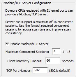
The Modbus/TCP Server Configuration options are used to setup and optimize the Modbus/TCP Server device driver in controllers that have an onboard Ethernet port. The Modbus/TCP Server can support up to 16 concurrent sessions with Modbus/TCP Clients.
Enable Modbus/TCP Server - this option completely enables or completely disables the controller's Modbus/TCP Server device driver. If this option is unchecked, the Modbus/TCP Server device driver is disabled, meaning the controller will not respond to any Modbus/TCP Client requests.
Maximum Concurrent Sessions - This value designates how many concurrent Modbus/TCP Server connections the device driver can handle. This can be any constant value between 1 and 16.
Note: Establishing a Modbus/TCP Server session requires processing time in the controller which will inevitably impact the scan time. If there are more Modbus/TCP Clients requesting connections than there are concurrent sessions available, then part of the processing includes shutting down the oldest session so that a new session can be opened. The need to forcibly close sessions so that new ones can be opened can be greatly minimized by setting this value to the maximum number of individual Modbus/TCP Clients that will be connecting to this controller at any given time.
Client Inactivity Timeout - specifies how much time (in seconds) to wait before closing the connection for a TCP Client that has stopped communicating. This can be any constant value between 0 and 65535.
TCP Port Number - designates the TCP port number that the Modbus/TCP Server device driver will use. The default value of 502 is the industry standard, and rarely will this value need to be changed. This can be any constant value between 0 and 65535.
Unit ID - designates the Unit ID that the Modbus/TCP Server device driver will use. This can be any constant value between 0 and 255.
Devices that connect with the Modbus/TCP protocol will only have access to the following blocks of memory in the controller (the ranges are numbered in decimal):
MI: Inputs, the default range is MI0 - MI1023
MC: Outputs, the default range is MC0 - MC1023
MIR: Input Registers: the default range is MIR0 - MIR2047
MHR: Holding Registers: the default range is MHR0 - MHR2047
Note: The size of the memory blocks available to the Modbus/RTU driver can be changed in the controller's Memory Configuration.
 TimeSync
Configuration:
TimeSync
Configuration:
The TimeSync Configuration option allows the Ethernet-equipped controllers on a network to automatically synchronize their internal real-time clocks.
A typical network will have one controller configured as a TimeSync Server, one or more controllers configured as TimeSync Alternates, and the remaining controllers configured as TimeSync Clients.
The TimeSync packet contains the current time from the TimeSync Server and the Update Interval so that Clients and Alternates will know when to expect the next TimeSync packet.
TimeSync packets are automatically sent by the TimeSync Server at the specified Update Interval. A TimeSync packet is also sent any time the real-time clock on the TimeSync Server is manually changed by Do-more Designer, or changed by a NETTIME (SNTP Client) instruction in the controller.
Note:
This feature uses TCP/IP broadcast packets to synchronize the real-time
clocks of the Clients and Alternates, which means that only controllers
within the TimeSync Server's broadcast
domain
There are four possible options for the TimeSync Configuration feature:
Disabled - the TimeSync feature in this controller is disabled, the controller's real-time clock will not be synchronized by a TimeSync Server. This is the default configuration for a controller.
Client - this controller will process TimeSync messages that are sent from a TimeSync Server. Each time a Client receives a TimeSync message it will update it's real-time clock with the real-time clock information in the TimeSync packet, set it's Status Bit ST23 ($TimeSynced) ON which indicates that the clocks have been synchronized, and begin timing down from the Update Interval so the Client will know when to expect the next TimeSync packet.
Server - this controller will generate TimeSync messages for other controllers on the network that are configured as Clients and Alternates. At each Update Interval or any time the Server's real-time clock is changed, a TimeSync Server will broadcast three TimeSync messages at five second intervals - three messages are sent to make sure that the Clients and Alternates receive at least one of the messages.
Alternate - this controller will normally function as a TimeSync Client but will promote itself to a TimeSync Server if there are no TimeSync packets received within the Update Interval. An Alternate will begin the process of promoting itself to a Server 15 seconds after the Update interval has expired.
Update Interval
- is used in the following three ways:
by a TimeSync Client - once a Client has its time synchronized, it sets its own $TimeSynced status bit and will begin using the Update Interval value as a countdown timer to know when to expect the next TimeSync packet. If that packet is not received before the Update Interval expires the controller will reset it's status bit ST23 ($TimeSynced) to indicate that the time is no longer synchronized.
by a TimeSync Alternate - once an Alternate has its time synchronized, it sets its own $TimeSynced status bit and will begin using the Update Interval value as a countdown timer to know when to expect the next TimeSync packet. If the next packet is not received before the Update Interval expires the Alternate will begin the process of promoting itself to a TimeSync Server.
by a TimeSync Server - designates the frequency that TimeSync packets are broadcast on the network
 Default
Watchdog Timeout:
Default
Watchdog Timeout:
The Software Watchdog Timeout specifies the maximum amount of time (in milliseconds) to allow for a single scan in the controller. If this value is exceed, the controller will immediately transition to STOP mode, an error message will appear in the System Information log, and the ERR LED on the front of the controller will be ON.
The Default Watchdog Timeout value is written to the system watchdog timer location $WatchdogTimeVal (DST23) on each STOP-mode to RUN-mode transition. This value can be changed at runtime by moving a new value into this location.
Default Timeout - specifies the number of milliseconds to use as the default watchdog timeout. This can be any constant value between 50 and 65535.
Note: controllers also have a Hardware Watchdog Timer that is used to put the controller into a safe mode if the operating system ever stops running for more than 2 seconds. Follow this link for details on Configuring the Hardware Watchdog Timer.
See Also:
CPU Configuration