Topic: DMD0299
MWX - Modbus Network Write
The Modbus Network Write (MWX) instruction is used to write data to a Modbus Server. It uses Modbus/TCP protocol to write data over the onboard Ethernet port, or Modbus/RTU protocol to write data over the onboard serial port or a port on an SERIO or SERIO-4 module.
The red triangle in the upper left corner of the status display indicates this is a Fully Asynchronous instruction.
Note: If the same Do-more Designer project will be using Modbus Write (MWX) instructions to write data to multiple Modbus/TCP Servers, the best performance will be had by creating a separate Modbus/TCP Client device for each of the Modbus/TCP Servers. For more information on creating devices see the Device Configuration help topic.
Except for broadcast messages, when the MWX instruction sends a query
to a server it expects a normal response. One of four possible events
can occur from the query:
If the server receives the query without a communication error, and can handle the query normally, it returns a normal response.
If the server does not receive the query due to a communication error, no response is returned. The MWX instruction will eventually process a timeout condition for the query.
Note: the timeout value is defined in the Modbus Client device.
If the server receives the query, but detects a communication error (parity, LRC, or CRC, no response is returned. The MWX instruction will eventually process a timeout condition for the query.
Note: the timeout value is defined in the Modbus Client device.
If the server receives the query without a communication error, but cannot handle it (for example, if the request is to write to a non-existent coil or register), the server will return an exception response informing the MWX instruction of the nature of the error. This exception response value from the server can optionally be stored in a memory location.
List of Modbus Exception Response Codes.

Element References:
Note: Use the F9 key (Element Browser) or Down-Arrow key (Auto-Complete) at any time to see a complete list of the memory locations that are valid in the current field of the instruction.
Device - designates which of the configured Devices
to read the data from. Before this instruction can select a Device, that
Device must be configured to accept data from an external source. Part
of the configuration for a device is assigning a name to the device. It
is that name which will show up in the Device selection drop-down menu.
For more information on configuring devices go to the Device
Configuration Section under System Configuration.
Ethernet Devices - selects one of the Devices configured to use the onboard Ethernet port (@IntEthernet) on the Do-more controller. Selecting a Device that uses an Ethernet port also selects the use of Modbus/TCP protocol.
Serial Port Devices - selects either the onboard serial port (@IntSerial), or one of the ports on a SERIO or SERIO-4 3-port serial I/O module. Selecting a Device that uses a serial port also selects the use of Modbus/RTU protocol.
create device - indicates that there are no Devices that have been configured to perform this instruction. For example, the CPU does not have an onboard Ethernet port, or the onboard serial port is NOT configured to be a Modbus Client. Selecting this entry will open the Create New Device dialog in the System Configuration so that a Modbus Client device can be created.
Modbus/TCP Addressing
IP Address - the IP Address of the Modbus Server that will receive the data
Note: Invoking the Element Browser (F9) for this field will bring up the IP Address Lookup utility that can find the IP Address for a given name.
TCP Port Number - the port number of the Modbus Server that will receive the data. The default value of 502 is typically the correct number for Modbus protocol.
Unit ID - (also
known as the Slave ID) designates the Unit ID of the Modbus Server that
will receive the data. This can be any constant value between 0 and 255.
Note: Unit ID
0 is the Modbus broadcast address, use this Address only to send the Write
Request to all Modbus RTU Servers on the network.
If this Modbus Network Write (MWX) instruction is configured to use a serial device, the Unit ID uniquely identifies the Modbus Server on the serial network.
If this Modbus Network Write instruction
(MWX) is configured to use an Ethernet Device, the Unit ID is unused.
Note: The one exception is a Modbus
Server that is a Modbus/TCP -to- Modbus/RTU gateway (such as our MB-Gateway).
In this instance the Unit ID will uniquely identify the Modbus/RTU Server
on the serial network side of the gateway.
Function Code - designates the Modbus function code to use. The following function codes are available in the drop-down menu:
5 - Write Single Coil
6 - Write Single Register
15 - Write Multiple Coils
16 - Write Multiple Registers
To Modbus Offset Address - designates the offset of the Modbus address where you want to write the data. This can be any constant value in the range of 1 to 65536.
Note: this field only specifies the offset for the location to begin reading, for example to write a value to Holding Register 40029 enter only the offset value 29, to write to the status of Coil 00017, enter only the offset value 17.
Number of Elements - designates the number of elements of the selected type to write.
If Function Code 5 or 15 is selected this selection defines how many coils to write. This can be any constant value in the range of 1 to 1976, or any readable bit location.
If Function Code 6 or 16 is selected this selection defines how many registers (16-bit words) to write. This can be any constant value in the range of 1 to 123, or any readable numeric location.
From Do-more Memory Address or Constant - designates one of the following two options:
the beginning address of the source data in the controller. This value must match the type specified in the Function Code, for example:
if Function Code 5 or 15 is selected the Memory Address value can be any readable bit location except struct fields
If Function Code 6 or 16 is selected the Do-more Memory Address value can be any readable numeric location except struct fields
Note: in most cases, the built-in Modbus memory blocks MC / MI / MIR / MHR should not be used as the source location for data sent by the MWX instruction because these memory locations are reserved for use by the Do-more's Modbus Server (Slave) function. Refer to the Modbus Memory Blocks diagram in the Memory Configuration section of the System Configuration for more information.
any single Constant value
Enable
- designates how this instruction is enabled. Select from one of the following:
Once on Leading Edge - select this option to have this instruction run to completion exactly one time. Typically, this will take more than one controller scan. Configured this way the Modbus Network Write (MWX) instruction is edge triggered
.
Continuous on Power Flow at Interval - select this option to have this instruction run as long as the instruction has power flow. After the Modbus Network Write (MWX) has initially run, if the instruction still has power flow, the instruction will remain enabled and will wait the specified amount of time before running again. The following options selects how much time (in milliseconds) to wait between successive runs.
Constant - specifies the interval time in Hours / Minutes / Seconds / Milliseconds.
Variable - This can be any readable that contains a value between 0 and 2,147,483,647 which represents the number of milliseconds to wait before running again. A value of 0ms means this instruction will be set to run on the next scan.
On Success - designates
one of the following two options if the Modbus Network Write operation
is successful:
SET BIT - The specific BIT location will be SET OFF when the Modbus Network Write (MWX) instruction is first enabled, and then SET ON if the operation is successful. This value can be any writable bit location.
JMP to Stage - JMP to the specified Stage. The target Stage must be in the same Program as the Modbus Network Write (MWX) instruction, you cannot specify a Stage in a different Program. This selection will function the same as a standalone Jump to Stage instruction. Click here for more information on the Jump To Stage instruction.
On Error - designates one of
the following two options if the Modbus Network Write operation is unsuccessful:
SET BIT - The specific BIT location will be SET OFF when the Modbus Network Write (MWX) instruction is first enabled, and then SET ON if the operation is unsuccessful. This value can be any writable bit location.
JMP to Stage - JMP to the specified Stage. The target Stage must be in the same Program as the Modbus Network Write (MWX) instruction, you cannot specify a Stage in a different Program. This selection will function the same as a standalone Jump to Stage instruction. Click here for more information on the Jump To Stage instruction.
Exception Response - enable this optional selection and enter a memory location to store the Modbus Exception Response for this instruction. This can be any writable numeric location.
Status Display:
The red triangle in the upper left corner of the status display indicates this is a Fully Asynchronous instruction.
Because Modbus protocol always works with Unsigned Word (16-bit) data,
this instruction will display the range specified in the From Do-more Memory Address field in an additional
field - called Do-more Range -
with the appropriate cast operators any time the entered element is NOT
an Unsigned Word type.
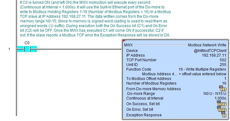
For example, If the MWX is writing two Holding Registers from D0, the Do-more Range field will display D0:UW0
- D0:UW1, which means that the first Holding Register value is will come
from Word 0 of D0, and the second Holding Register value will come from
Word 1 of D0.
In the example to the right the specified range is N0 - N19, the N range contains Signed Word values, so the :U cast operator is added to the display in the Do-more Range field as N0:U - N19:U.
For more information on casting, refer to the help topic on Casting.
See Also:
MWX - Modbus Network Write
Modbus Exception Response Codes
Example:
Description of a Typical Modbus Network Write (MWX) Stage Diagram:
 To the right is a stage diagram showing a typical
sequence that monitors a 3rd-party Modbus TCP slave and reads up a new
recipe whenever it becomes available.
To the right is a stage diagram showing a typical
sequence that monitors a 3rd-party Modbus TCP slave and reads up a new
recipe whenever it becomes available.
Initially the NewRec (New Recipe) stage monitors a bit from the slave. When this bit comes ON, RecipeRdy (Recipe Ready) causes the transition to the RDRec stage.
The RDRec (Read Recipe) reads the new recipe from the slave. When this completes, RecipeRD (Recipe Read) causes the transition to the RSTRec stage.
The RSTRec (Reset Recipe) writes a bit to the slave to inform it the recipe has been read successfully. When this write is complete, RecipeRST (Recipe Reset) causes a transition to the RSTMon stage.
The RSTMon (Reset Monitor) stage monitors a bit from the slave to confirm the slave heard the reset. When this bit comes ON, MonRST (Monitor Reset) causes a transition back to the NewRec stage to repeat the process and wait for the next new recipe.
Description of a Typical Modbus Network Write (MWX) Stage Ladder:
 To the right is a ladder program that
is equivalent to the above stage diagram. It utilizes both the Modbus
Network Read (MRX) and Modbus Network Write (MWX) instructions to monitor
a 3rd-party Modbus TCP slave and read up a new recipe whenever it becomes
available.
To the right is a ladder program that
is equivalent to the above stage diagram. It utilizes both the Modbus
Network Read (MRX) and Modbus Network Write (MWX) instructions to monitor
a 3rd-party Modbus TCP slave and read up a new recipe whenever it becomes
available.
A summary of the master/slave interaction is as follows:
The master monitors Modbus Input bit 1.
The slave formulates a new recipe and stores it in Modbus Input Register range 1-16.
The slave sets Modbus Input bit 1 ON when the recipe is ready and begins to monitor his own Modbus Coil 1 to know when the master has read the new recipe up.
The master sees Modbus Input bit 1 turn ON and reads up the new recipe from Modbus Input Register range 1-16 and stores it in his memory range RecipeVar1-RecipeVar16.
The master then sets the slave's Modbus Coil 1 to inform the slave he has read up the new recipe and begins to monitor Modbus Input bit 2 to know the slave heard him.
The slave sees his Modbus Coil 1 turn ON and turns ON his Modbus Input bit 2 to inform the master he is now formulating the next recipe.
The master sees Modbus Input bit 2 come ON and can now repeat the cycle (return to step 1 above).
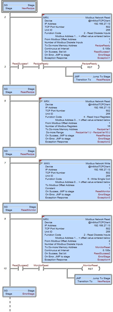
NewRecipe is the initial stage. The MRX instruction is set to execute "Continuous at Interval 0.100s" to read a particular Modbus Input from the slave. This is the bit the slave will set when a new recipe has been stored and is ready for the Do-more PLC to read it up. The MRX reads this bit and stores it in RecipeReady bit. Upon the successful completion of each read the ReadSuccess1 bit will come ON. When there has been a successful read and the RecipeReady bit is ON, Rung 3 resets the RecipeReady bit back OFF (in preparation for the next cycle) and transitions to the ReadRecipe stage. If any one of these reads fails, the MRX instruction will transition to the ErrorStage where the error can be assessed (e.g. evaluation of the Exception Response, Exception1 value).
The ReadRecipe stage executes the MRX instruction once to read up the new recipe from Modbus Input Registers 1-16 and stores them in Do-more memory range RecipeVar1-RecipeVar16. Upon a successful read, the MRX transitions to the ResetRecipe stage. If the read failed, the MRX instruction will transition to the ErrorStage where the error can be assessed (e.g. evaluation of the Exception Response, Exception2 value).
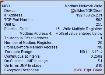
The ResetRecipe stage executes the MWX instruction once to write to a single Modbus Coil to inform the slave the new recipe has been read up successfully. Upon a successful read, the MWX transitions to the ResetMonitor stage. If the write failed, the MWX instruction will transition to the ErrorStage where the error can be assessed (e.g. evaluation of the Exception Response, Exception3 value).
The ResetMonitor stage monitors a feedback bit from the slave that the slave should use to inform the Do-more PLC that it "heard" the recipe read was successful and that the slave can now make preparations for the next recipe. The MRX reads this bit (Modbus Input 2) and stores it in MonitorReset bit. Upon the successful completion of each read the ReadSuccess2 bit will come ON. When there has been a successful read and the MonitorReset bit is ON, Rung 10 resets the MonitorReset bit back OFF (in preparation for the next cycle) and transitions back to the initial NextRecipe stage. If any one of these reads fails, the MRX instruction will transition to the ErrorStage where the error can be assessed (e.g. evaluation of the Exception Response, Exception4 value).
The ErrorStage should have code in it (not shown here) that evaluates the various errors that can occur in this example.
Example 2 of 2: