Topic: DMD0251
Memory Configuration
The Memory Configuration dialog page displays all of the currently configured
memory blocks and heap items
This dialog page also provides a facility to modify the existing configuration
by:
creating additional memory blocks and heap items
editing the size of the memory blocks and heap items
changing the retentive memory settings of the memory blocks and heap items
deleting unused memory blocks or heap items
User-defined Memory Blocks must be created before they can be used in a Do-more Designer project. User-defined heap items can be created during an editing session. Creating new Memory Blocks, changes to existing memory blocks, and creating new Heap Items make changes to the system configuration. The System Configuration CANNOT be downloaded to the controller while it is in RUN mode. The controller will need to be placed in Program mode while the new system configuration is downloaded. Creating the heap items before they are referenced in the project will preserve the ability to perform run-mode edits.
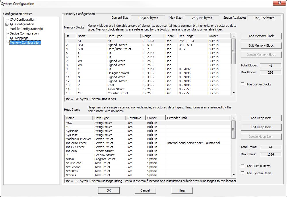
Current Size: - displays the amount of memory consumed by the memory blocks and heap items in the current memory configuration.
Max Size: - displays the maximum size available for memory blocks and heap items, this value is dependant on the memory size of the Do-more controller.
Space Available: - displays the space that remains for memory blocks and heap items.
Adding, Editing, and Deleting Memory Blocks
Total Blocks - displays the number of currently defined memory blocks
Max Blocks - displays the maximum number of memory blocks the controller will allow
Hide Built-in Blocks - optionally removes the Built-in memory from the list, leaving only the user-defined memory blocks in the list.
Add / Edit Memory Block
- invoke a dialog used to create new memory blocks or modify the currently
highlighted memory block.
Delete Memory Block - built-In memory
blocks can not be deleted, only user-created memory blocks can be deleted.
 Block Settings - define
the characteristics of the memory block
Block Settings - define
the characteristics of the memory block
Name - specifies the name of the block. Block names must be unique, and consist of 1 to 16 characters (A-Z, a-z; no numbers, no spaces).
Data Type - designates the type of data the block will contain:
Bit - each element in the block can is a Bit
Unsigned Byte - each element in the block is an Unsigned Bytes that can hold a value of 0 to 256
Signed Byte - each element in the block is a Signed Bytes that can hold a value of -128 to 127
Unsigned Word - each element in the block is an Unsigned Word that can hold a value of 0 to 65535
Signed Word - each element in the block is a Signed Word that can hold a value of -32768 to 32767
Signed DWord - each element in the block is a Signed Word that can hold a value of -2,147,483,648 to 2,147,483,647
Real - each element in the block is Real (floating point) location that can hold a value of -3.4e+038 to 3.4e+038
Timer Struct - each element in the block is a Timer Struct
Counter Struct - each element in the block is a Counter Struct
String - each element in the block is a Strings
PID Struct - each element in the block is a PID Struct
Date/Time Struct - each element in the block is a Date/Time Struct
Task Struct - each element in the block is a Task Struct
Rampsoak Struct - each element in the block is a Ramp/Soak profile Struct
Program - each element in the block is a Program Struct
DeviceRef Struct - each element in the block is a DeviceRef Struct
Drum Struct - each element in the block is a Drum Struct
String Length - (only valid if the Data Type is String) - specifies the length of each String in the Block
Block Size - specifies the desired number of elements in the Block. Memory blocks are allocated on DWord (32-bit, 4-byte, or 2-Word)
Radix - specifies the desired radix (Decimal or Octal) of the memory block
Retentive
Range Settings - Memory marked as retentive
will hold its state through a power cycle. The status of memory NOT marked
as retentive will be cleared at power up. Select one of the following
three options:
Nothing Retentive - none of the memory locations in the memory block will be retentive
Entire Block Retentive - all of the memory locations in the memory block will be retentive
This Range Retentive - this single range of the memory locations in the memory block will be retentive
From Block ID - the ID of the first element in the range to make retentive
To Block ID - the ID of the last element in the range to make retentive
Adding, Editing, and Deleting Heap Items
Total Items - displays the number of currently defined heap items
Max Items - displays the maximum number of heap items the Do-more controller will allow
Hide Built-in Items - optionally removes the Built-in heap Items from the list, leaving only the user-defined and System memory blocks in the list.
Hide System Items - optionally removes the System-created heap items from the list, leaving only the user-defined and Built-in heap items in the list.
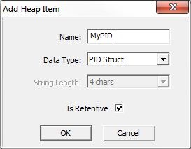
Add / Edit Heap Item - invoke
a dialog used to create new heap items or modify the currently highlighted
heap item
Delete Heap Item - built-In heap items can not be deleted, only
user-created items can be deleted.
 Add / Edit heap item
Settings:
Add / Edit heap item
Settings:
Name - specifies the name of the heap item. Heap Items names follow Nickname rules
Data Type - designates the data type of the heap item:
Timer Struct - the heap item will be a Timer Struct
Counter Struct - the heap item will be a Counter Struct
String - the heap item will be a String
PID Struct - the heap item will be a PID Struct
Date/Time Struct - the heap item will be a Date/Time Struct
Task Struct - the heap item will be a Task Struct
Rampsoak Struct - the heap item will be a Ramp/Soak profile Struct
Program - the heap item will be a Program Struct
DeviceRef Struct - the heap item will be a DeviceRef Struct
Drum Struct - the heap item will be a Drum Struct
Is Retentive - heap items marked as retentive will hold their values through a power cycle. Heap items NOT marked as retentive will be cleared at power up.
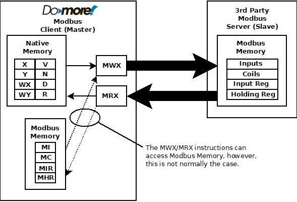
Modbus Memory Blocks
One part of the overall security system is preventing external devices (operator panels, HMIs, etc.) from being able to directly control the PLC's I/O and memory. When operating as a Modbus Server (Slave) - either Modbus/TCP or Modbus/RTU - the Do-more controller does not allow external devices that communicate through the Modbus protocol to have direct access to the controller's internal memory and I/O.
All Modbus Read and Write requests from external devices will be serviced from the four built-in memory blocks that are reserved for use by the Do-more controller's Modbus Server (Slave) device, they are: MC (Modbus Coils), MI (Modbus Inputs), MHR (Modbus Holding Registers), and MIR (Modbus Input Registers). The Modbus Server only has access to the MI, MC, MIR, and MHR memory blocks in the controller, it cannot access the other (native) memory blocks or the I/O in the controller.
The ladder logic instructions have access to all of the native memory AND the Modbus memory, so the Modbus memory locations can be referenced in place by the instructions. If data in the Modbus memory locations need to be converted (for example if it has to be byte-swapped, or converted to floating point) before it can be used, the Subscribe - Translate to Do-more instruction can be used to convert the data and store the converted data in Native memory, and the Publish - Convert from Do-more instruction will can be used to convert data from native memory locations as required and store the converted values in Modbus memory.
The default configuration of the four blocks of Modbus memory has 1024 elements for the BIT ranges and 2048 elements for the numeric range elements, using decimal addressing, so there is no mapping of the Modbus memory required for the external read and write requests. The size of these ranges can be increased if needed.

As stated above, when operating as a Modbus Client, using the MRX - Modbus Network Read and MWX - Modbus Network Write instructions have access to all of the native memory as well as the Modbus memory. And while it is possible to use the MC, MI, MHR, MIR memory locations as destination registers for MRX instructions, and as source registers for MWX instructions, in most cases it is not advisable to do so because that memory is reserved for use by the Modbus Server.
DirectLOGIC Memory Blocks
The same security system is in place when the Do-more controller is operating as a DirectLOGIC Server (Slave) meaning that it does not allow external devices that communicate through the K-Sequence protocol, or communication modules that work with DL processors - like the ERM and ECOM modules - to have direct access to the controller's internal memory and I/O.
All K-Sequence Read and Write requests from external devices, or backplane data requests form an ERM or ECOM will be serviced from the four built-in memory blocks that are reserved for use by the Do-more controller's DirectLOGIC Server (Slave) device, they are: DLC (Coils), DLX (Inputs), DLY (Outputs), DLV (Registers). The DirectLOGIC Server only has access to the DLC, DLX, DLY, and DLV memory blocks in the controller, it cannot access the other (native) memory blocks or the I/O in the controller.
The ladder logic instructions have access to all of the native memory AND the DirectLOGIC, so the DirectLOGIC memory locations can be referenced in place by the instructions. If data in the DirectLOGIC memory locations needs to be converted (for example if it has to be byte-swapped, or converted from BCD) before it can be used, the Subscribe - Translate to Do-more instruction can be used to convert the data and store the converted data in Native memory, and the Publish - Convert from Do-more instruction will can be used to convert data from native memory locations as required and store the converted values in DirectLOGIC memory.
The default configuration of the four blocks of DirectLOGIC memory has 512 elements for the BIT ranges and 2048 elements for the numeric range, using octal addressing, so there is no mapping of the DirectLOGIC memory required for the external read and write requests. The size of these ranges can be increased if needed.

As stated above, when operating as a DirectLOGIC Client, using the DLRX - DirectLOGIC Network Read and DLWX - DirectLOGIC Network Write instructions have access to all of the native memory as well as the DirectLOGIC memory. And while it is possible to use the DLX, DLY, DLC, and DLV memory locations as destination registers for DLRX instructions, and as source registers for DLWX instructions, in most cases it is not advisable to do so because that memory is reserved for use by the DirectLOGIC Server.

See Also:
Memory Configuration