Topic: DMD0249
I/O Configuration
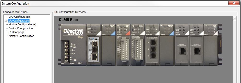
I/O Configuration:
The Top level of the I/O Configuration dialog displays a graphical view of the I/O Base with the Do-more controller in the CPU slot, and all of the I/O modules that are in the base.
I/O Module Error Handling
This is a good point to discuss how the Do-more controller handles runtime reporting of errors from the I/O Modules that are under the control of the I/O Masters. There is a three level reporting scheme that reports I/O module errors at increasing levels of definition. This allows the programmer to handle these I/O errors at whatever level is deemed appropriate.
The highest level reported is $IOError
(ST152), which is a single bit location that will be ON any time
any of the I/O Masters in the system is reporting an error from one or
more of its modules. The
The middle level reported is $IOMasterErrors
(DST28), which is a DWord (32-bit) location that has one bit assigned
to each I/O Master in the system. The individual bit for an I/O Master
will be ON if any I/O
Bit 0 is assigned to the LocalIOMaster, which
controls the I/O modules that are in the base with the Do-more
controller.
Bits are assigned to additional I/O Masters in the order that they appear in the I/O Configuration.
The lowest level is reported in a structure for each I/O Master. An I/O Master can manage up to 128 slots of I/O modules, so each structure has four DWord (32-bit) locations, with one bit assigned to each slot. For example, the LocalIOMaster has the following four structure members:
LocalIOMaster.Slot0_31 - reports errors for slot 0 through slot 31
LocalIOMaster.Slot32_63 - reports errors for slot 32 through slot 63
LocalIOMaster.Slot64_95 - reports errors for slot 64 through slot 95
LocalIOMaster.Slot96_128 - reports errors for slot 96 through slot 128
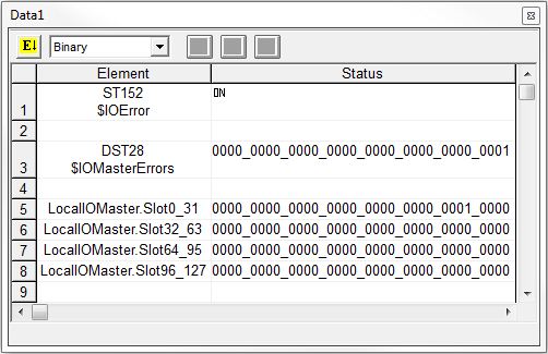
The following Data View show these reporting elements reporting the following condition:
There is an I/O Error ($IOError is ON).
The I/O Master that is reporting the error is LocalIOMaster (bit 0 of IOMasterErrors is ON).
The I/O Module that is reporting the error is in slot 5 (bit 5 of LocalIOMaster.Slot0_31 is ON).
The final piece of information that may be required is the error information from the module itself. The amount of this data, the type of data, and how that data is presented to the Do-more controller depends on the module.
For modules that report error information through status bits and/or alarm bits (for example the analog input modules), those bits are automatically placed in the Discrete Input range (X) at the same time the values for the actual I/O channels are placed in their proper memory locations - refer to the chart for Analog I/O Module Mapping and Discrete I/O Module Mapping for details on the number of alarm and status bits that are allocated for a particular module.
Details on what each of those bits indicates is module-specific, that information must be referenced from the Analog and Discrete I/O Module chapters of the Do-more H2 Series PLC Hardware User Manual (Automationdirect.com Part #: H2-DM-M).
DL205 Local I/O Masters:
Expanding the Top Level will display all of the I/O Masters in the current system.

This list will contain the following:
Local I/O Master that controls backplane communication
Expansion I/O Masters which control communication to local expansion I/O
Remote I/O Masters which control communication to Ethernet remote I/O controllers
In this case the only I/O Master is the DL205 Local I/O Master, and
the only configuration that can be done is setting the I/O Configuration
Mode to one of the following:
Auto - in this mode the controller will scan the backplane for I/O modules and automatically create an I/O configuration that matches the modules found.
Manual - in this mode the user can change the I/O Configuration by adding modules and/or deleting modules. On Program-mode to Run -mode transitions the controller will compare the manually adjusted I/O configuration to the installed I/O modules list, and these must match before the controller can go into Run mode.
DL205 Base Configuration:
Expanding each of the I/O Masters will display a graphical view of each base and the I/O modules that are installed. Hovering the mouse cursor over the top section of an I/O module will display the part number of the module in that slot. Since the DL205 system shares part numbers among modules with the same I/O, instead of a single part number, you will typically see a list of all the modules with the I/O that match the I/O detected in that slot.

Manual I/O Configuration Options:
Manual Base Scan - If the I/O
Master's
Base Size - since the DL205 system cannot automatically detect the size (number of slots) in a given base, this selection provides a way to change the graphical view so that it matches the actual size of the base. Select the 3 Slot, 4 Slot, 6 Slot, or 9 Slot option from the drop-down list - the list of optional base sizes will change based on the number of modules detected in the base.
How to Delete the Configuration for an Installed Module
If the I/O Master's Configuration Mode is set to "manual", right-clicking on the installed module's graphic and select Delete Module from the pop-up menu will remove the current I/O module definition from the I/O configuration.
Marking a Module Configuration as Optional
If the I/O Master's Configuration Mode is
set to "manual", right-clicking on the installed module's graphic
and select Optional from the pop-up
menu will mark this module as Optional meaning that it will not be considered
when the manual I/O configuration is compared to the I/O configuration
read from the system during a Program-mode to Run-mode transition. The
I/O space consumed by a module configured as optional is retained so that
the I/O mapping does not change.
Note: The instruction HWINFO - Get Hardware Information can be used
to detect the presence of I/O modules marked as 'Optional' as a way to
programmatically control optional execution schemes.
Note: I/O modules that are configured
to be optional will be marked with the word "*Optional*" in
yellow on the graphical view.
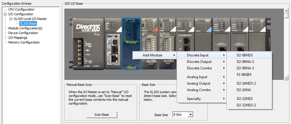
How to Manually Add a Module
Right-clicking on an Empty Slot will display the Add Module dialog, which will then display a selection of I/O Module classes. Select the appropriate class, and follow on to display a list of the I/O modules in that class. Select the desired module by part number in that list and that module will be added to the configuration.
See Also:
I/O Configuration