Topic: DMD0141
PID - Closed Loop Controller
The Closed Loop Controller (PID) instruction implements a Proportional, Integral, and optionally Derivative control algorithm in the Do-more controller. The PID instruction calculates an "error" value as the difference between a measured process variable (PV) and the desired setpoint (SP). The PID controller attempts to minimize the error by adjusting the PID Output, which then affects the process control inputs.
The general function of the PID instruction is to use a continuous feedback loop to keep the process flowing normally by taking corrective action whenever there is a deviation from the desired value (SP) of the process variable (PV) such as, rate of flow, temperature, voltage, etc.
The resulting .Output value is calculated as a percentage value in the range of 0.0 to 100.0.

Inputs:
The PID Loop's mode (Auto or Manual) is controlled by the power-flow of the PID instruction's single ladder logic input (A/M).
If the input logic is ON, the PID instruction is enabled and the loop's Mode is set to Auto.
If the input is OFF, the loop's Mode is set to Manual. In Manual mode the loop IS NOT running the PID calculation, meaning the .Output value remains unchanged by the loop.
It is expected that an operator or other intelligent source is manually controlling the output by observing the PV and writing data to .Output as necessary to keep the process under control.
Parameters:
Note: Use the F9 key (Element Browser) or Down-Arrow key (Auto-Complete) at any time to see a complete list of the memory locations that are valid in the current field of the instruction.
PID Struct - designates a name
to uniquely identify the PID Loop. This can be a either a new heap item
Note: choosing to create a new heap item will change the System Configuration. Changes to the System Configuration can only be saved to the Do-more controller when it is in PROGRAM mode. Additional Run mode updates can not be performed until these System Configuration changes have been saved to the controller. For more information on heap items and pre-allocating one or more PID loops refer to the Memory Configuration section in the System Configuration utility.
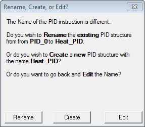 If the PID Struct field
is changed, the dialog at the right will be displayed.
If the PID Struct field
is changed, the dialog at the right will be displayed.
Rename - choosing this option will simply rename the existing PID Struct, this will not cause a change to the System Configuration. One situation where this would occur is after a copy/paste operation of an existing PID structure and the Struct of the pasted PID loop needs to be changed
Create - choosing this option will create a new heap item, and the existing PID Struct will not be affected. This will cause a change to the System Configuration which can only be saved to the Do-more controller when it is in PROGRAM mode
Edit - choosing this option will return to the instruction editor
Loop Algorithm - designates
the type of calculation to be done.
Position - select this option to compute the actual position. This is the choice for most applications which include heating and cooling loops as well as most position and level control loops.
Velocity - select this option to compute the change in position. A typical velocity control will consist of a process variable such as a flow totalizer in a flow control loop.
Control Output - designates
the relationship between the Output value and the Error value
Forward Acting - select this option if the output is driven in the same direction as the error. A forward (direct) acting control loop means that whenever the .Output value increases, the process variable will also increase.
Reverse Acting - select this option if the output is driven in the opposite direction from the error. A reverse acting control loop means that whenever the .Output value increases, the process variable will decrease.
Initialization Mode - A bumpless
transfer from manual mode to automatic mode is achieved by preventing
the control output from changing immediately after the mode change.
Set SP equal to PV - Automatically sets the output (M) equal to the bias (Mx) and the setpoint (SP) equal to the process variable (PV) when control switches from manual to automatic.
Bumpless - Automatically sets the output (M) equal to the ( bias (Mx) - Error) to the output (M) when control switches from manual to automatic
Other Options - designates optional
processing of the Error term
Use Error Squared - A loop with Error Squared enabled is less responsive than a loop using just the error value; however, it will respond faster with a large error. The smaller the error, the less responsive the loop. The sign of the Error term is maintained in the Error Squared value.
Enable Error Deadband - With error deadband control, no control action is taken if the Process Variable (PV) is within the specified deadband area around the setpoint. The value for the deadband is set through <PID reference>.ErrorDB. The error deadband is the same above and below the setpoint. Once the PV is outside of the error deadband around the setpoint, the entire error is used in the loop calculation.
Note: The error will be squared first if both Error Squared and Error Deadband are selected.
Disable Bias Freeze - if enabled the algorithm will continue changing the bias even though the computed normalized output goes outside the range of 0.0 to 100.0.
Scale to .PV - enables optional scaling of the raw input value to engineering units before it's used as the Process Variable (.PV)
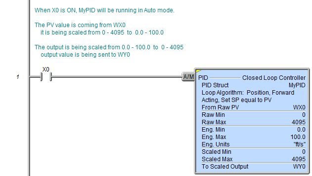
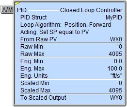
From Raw PV - designates the raw input location to use as a basis for the Process Variable (.PV). This can be any readable numeric location. This is typically a raw analog input value (WX).
Raw Min - the minimum raw data point to use in the scaling algorithm. This can be any constant value or any readable numeric location.
Raw Max - the maximum raw data point to use in the scaling algorithm. This can be any constant value or any readable numeric location.
Eng Min - the engineering data point that equates to the Raw Min parameter value to use in the scaling algorithm. This can be any constant value or any readable numeric location.
Eng Max - the engineering data point that equates to the Raw Max parameter value to use in the scaling algorithm. This can be any constant value or any readable numeric location.
Eng Units - designates an 8character string that will be displayed on the PID View. This can be a string literal
any of the system-defined Short Strings, or system-defined Long Strings, or any user-defined Strings.
Scale from .Output % - enables optional scaling of the Output value (.Output) before it's stored in the designated analog output location. The raw .Output value has a range of 0.0 to 100.0.
Scaled Min - the minimum scaled value to use in the scaling algorithm corresponding to when .Output value equals 0.0. This can be any constant value or any readable numeric location.
Scaled Max - the maximum scaled value to use in the scaling algorithm corresponding to when .Output value equals 100.0. This can be any constant value or any readable numeric location.
To Scaled - designates the output location to store the scaled Output value. This can be any writable numeric location.
Status Display:
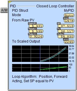
The yellow triangle in the upper left corner indicates this is a Multi-Scan instruction.
When the ladder status is ON (Debug-> All Status On), in addition to the key PID numeric status values being displayed, the Closed Loop Controller instruction also displays two small trends that show the PID structure's values graphically. The first graph shows the Set Point and Process Variable input values. The second graph shows the Control Output value.
To turn off the trend display, go to the View-> Options menu, select the Ladder tab, then uncheck the Show Trend Status selection.
The Closed Loop Controller instruction provides several status values ("dot" fields) that can be used elsewhere in your ladder program. Their values are updated each time the instruction is processed. The syntax for using them is <PID struct>.<struct member>. The following is a list of the"dot" fields that are programmatically accessible for each Closed Loop Controller instruction:
.PV - the process variable
.SP - the setpoint value
.Gain - the Proportional gain value (P)
.Reset - the reset (or Integral) value
.Rate - the rate (or Derivative) value
.Bias - the bias term, used in the Integral term calculation and to provide bumpless mode
.Output - the loop calculated output value as a percentage in the range 0.0 to 100.0
.ErrorDB - the error deadband value
.DGainLmt - the derivative gain limit value
.SampleTime - the calculation's sample time value in milliseconds
.Mode - will be ON if the loop is in Auto mode
.AutoTuning - will be ON if the loop is currently in an auto-tune cycle
.AutoTuneComp - will be ON if the auto-tune cycle completed successfully
.AutoTuningErr - will be ON if the auto-tune cycle did not complete successfully
.RanThisScan - will be ON if the loop calculation was performed on the current PLC scan
.Tune - this bit is set ON during an auto-tune cycle
.TuningAlg - specifies the auto-tune algorithm: 0 = Closed Loop, 1 = Open Loop
.TunedParms - specifies which Autotune calculation to use: 0 = PI, 1 = PID
.LastError - contains the last error or error squared value computed by the Loop
A complete discussion of these structure fields can be found in the PID Loop Help section.
Data View Display Formats:
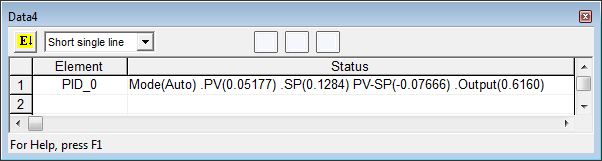
The Data View dialog in Do-more Designer has four display formats for a Closed Loop Controller (PID) structure, two that offer different orientations (single line and multi-line) and two that offer different numbers of data points (short and long).
Note: These formats are for display purposes only, the PID Loop variables cannot be edited when displayed using any of the formats. Use the individual structure members individually to change any writable member.
Short Single Line:
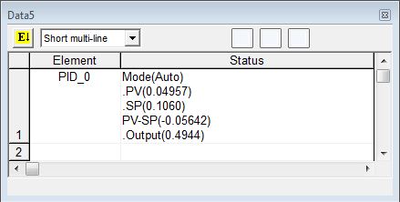
Short Multi-Line (the default):
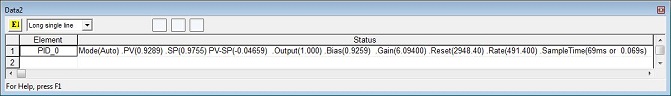
Long Single Line:
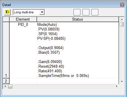
Long Multi-Line:
Related Instructions:
PID - Closed Loop Controller
See Also:
Related Topics:
Rung Example: