Topic: DMD0137
FILTER - First Order Filter
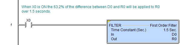
The First Order Filter (FILTER) instruction performs a continuous filtering operation on the input value. This operation applies 63.2% of the difference between the In value and the Out value to the Out value over the duration of the Time Constant.

Parameters:
Note: Use the F9 key (Element Browser) or Down-Arrow key (Auto-Complete) at any time to see a complete list of the memory locations that are valid in the current field of the instruction.
Time Constant - designates the amount of time in seconds over which to apply the filter. This can be any positive constant value or any readable numeric location.
In - designates the location that contains the value to be filtered. This can be any readable numeric location.
Out - designates the location to store the filtered value. This can be any writable numeric Real location.
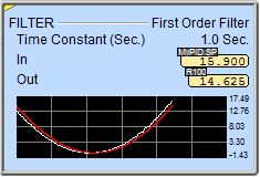
The charts below show the output response to a step input when using
the FILTER instruction. At one times the Average Time Constant, 63% of
an input change is achieved at the output. At five times the Average Time
Constant value, 100% of the input change is achieved at the output.

Status Display:
The yellow triangle in the upper left corner indicates the First Order Filter is a Multi-Scan instruction.
When the ladder status is ON (Debug-> All Status On), in addition to the standard status values being displayed, the 1st Order Filter instruction also displays a small trend that shows the instruction's values graphically.
To disable the display of the trend go to the View-> Options menu, select the Ladder tab, then uncheck the Show Trend Status selection.
See Also:
FILTER - First Order Filter
Rung Example: