Topic: DMD0504
Stage Transition Instructions
Using a "Jump" Operation to Transition Between Stages
The previous examples have used the Jump to Stage (JMP) instruction to transition between stages. Recall that the Jump to Stage (JMP) instruction does two things: it deactivates the stage in which the instruction occurs, and activates the stage referred to in the Jump to Stage (JMP) instruction.
Please Read This Carefully &endash; The functionality of the Jump to Stage (JMP) instruction can be easily misunderstood. The term ”jump” sounds like the instruction would function like a GOTO instruction when executed, that is, processing would immediately begin at the target of the "jump" &endash; this is wrong! Here are some general rules to keep in mind when dealing with the Jump to Stage (JMP) and Jump to Multiple Stages (SGDIVRG) instructions:
The Jump to Stage (JMP) and Jump to Multiple Stages (SGDIVRG) instructions immediately disable the stage in which they occur. The effect of being disabled will take effect on the subsequent scan, meaning the stage that executed the Jump to Stage (JMP) instruction will be inactive - and thus bypassed - on the next PLC scan.
The target stage in the Jump to Stage (JMP) instruction will be enabled immediately. All of the target stages in the Jump to Multiple Stages (SGDIVRG) instruction will be enabled immediately. What this means in terms of program execution is that the target stage(s) will execute when the PLC scan gets to them.
All of the rungs in the stage are executed during the current scan, even any rungs that follow the Jump to Stage (JMP) and Jump to Multiple Stages (SGDIVRG) instructions.
All output coils used in a stage will be automatically turned off on the scan immediately following the scan in which the Jump to Stage and Jump to Multiple Stages (SGDIVRG) instructions are executed. We will discuss this more completely in a later section, but for now, it is sufficient to know that all output coils used in a stage will be automatically turned off once the stage has been disabled.
Generally speaking, if an instruction has a single input it will be reset when the stage is disabled. If the instruction has multiple inputs, with one of them being a reset input, it will not be reset when the stage is disabled. This too will be discussed in more detail later.
Refer to the two-stage program examples below. Here’s how the Jump to Stage (JMP) instruction functions:
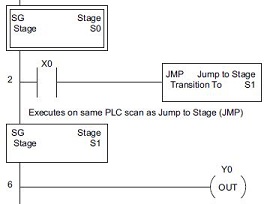 In this example, stage S0 is enabled. When X0 comes
ON the Jump to Stage (JMP) S1 executes. Stage S1 is executed during the
same scan turning Y0 ON.
In this example, stage S0 is enabled. When X0 comes
ON the Jump to Stage (JMP) S1 executes. Stage S1 is executed during the
same scan turning Y0 ON.
This is because stage S1 follows stage S0.
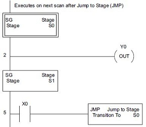 In this example, stage S1 is enabled. When X0 comes
ON the Jump to Stage (JMP) S0 executes. However, Stage S0 is executed
the next scan. Thus Y0 will come
ON during the next scan not the same scan the JMP was executed.
In this example, stage S1 is enabled. When X0 comes
ON the Jump to Stage (JMP) S0 executes. However, Stage S0 is executed
the next scan. Thus Y0 will come
ON during the next scan not the same scan the JMP was executed.
This is because stage S0 precedes stage S1.
Using an "Enable / Disable" Operation to Transition Between Stages
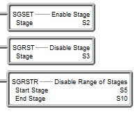 There are three additional stage programming instructions
that allow for stage-to-stage transitions: they are Enable Stage (SGSET),
Disable Stage (SGRST), and Disable Range of Stages (SGRSTR).
There are three additional stage programming instructions
that allow for stage-to-stage transitions: they are Enable Stage (SGSET),
Disable Stage (SGRST), and Disable Range of Stages (SGRSTR).
Whereas the Jump to Stage (JMP) and Jump to Multiple Stages (SGDIVRG) instructions enable the target stage and disable the current stage, the Enable Stage (SGSET) and Disable Stage (SGRST) instructions only enable and disable the target stage; they do not necessarily disable the current stage. The Disable Range of Stages (SGRSTR) disables a range of consecutive stages.
A Jump to Stage (JMP) instruction is functionally equivalent to an Enable Stage (SGSET) of the target stage paired with a Disable Stage (SGRST) of the current stage.
Using a "Converge" Operation to Transition Between Stages
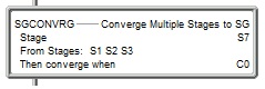 There is a special stage programming instruction
that allows for multiple stages that are enabled to be converged to one
stage when all stages in its list are enabled, and a condition is non-zero
(TRUE / ON). It is called Converge Multiple Stages to SG (SGCONVRG).
There is a special stage programming instruction
that allows for multiple stages that are enabled to be converged to one
stage when all stages in its list are enabled, and a condition is non-zero
(TRUE / ON). It is called Converge Multiple Stages to SG (SGCONVRG).
The instruction is a stage itself (e.g. S7 in pic). In the picture at the right, when stages S1, S2 and S3 are all enabled, and C0 is ON, then stages S1, S2 and S3 are all disabled and stage S7 is enabled. This one instruction is equivalent to using a rung in each of the stages (S1, S2 and S3) that has a normally-open contact C0 turning ON an SGRST disabling themselves, and then using an SGSET enable stage S7.
Stage Programming Concepts
Example 1 - A Simple 2-State Process
Stage Transition Instructions
Example 2 - A Lamp On/Off Controller
Example 3 - A Garage Door Opener
Review - Steps to Writing Successful Stage Programs
Stage Instructions in the Do-more Controller