Topic: DMD0501
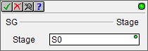
SG - Stage
The Stage (SG) instruction marks the beginning of a stage in a Program code block.
Note: The Stage (SG) instruction is a 'power-rail' instruction. And while all of the Stage instructions are displayed in the left-most column of the ladder diagram (the power rail), they are created in the right-most column of the ladder logic diagram (the output column). This makes creating Stage instructions in Do-more Designer a bit counter-intuitive because the first step is to position the edit cursor in the output column of the ladder logic diagram (the far right) instead of positioning it against the power rail (the far left).
Any time that a Stage is disabled, for example, by a Jump To Stage (JMP), an Indexed Jump (JMPI), a Disable Stage (SGRST), or a Disable Range of Stages (SGRSTR) instruction, the following actions will occur:
All output coils (OUT) within that Stage will be turned off
All Timers within that Stage will be reset
Edge triggered contacts will be turned off
Edge triggered instructions will be reset
Rising-edge triggered contacts will energize and edge-triggered inputs on instructions that have them will be ON during the first scan of the ladder logic in a Stage if they are ON when the Stage is first enabled..
Note: All Stage programming instructions must be entered in a Program code block; Stage instructions cannot be placed in a Task code block.
For a complete discussion on Stage Programming concepts and how to use the Stage programming instructions effectively, refer to the Help Topic on Stage Programming Concepts.
Parameters:
Note: Use the F9 key (Element Browser) or Down-Arrow key (Auto-Complete) at any time to see a complete list of the memory locations that are valid in the current field of the instruction.
Stage - designates the reference number of the Stage to create. The Stage reference can be entered using its fully qualified name - for example MyProgram.S0 through MyProgram.S127 - or simply its Stage number - for example S0 through S127.
Note: Stage programming instructions can only reference Stages in the same Program code block, they cannot reference Stages in a different Program code block.
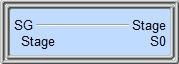
The first SG instruction in a Program code block, regardless of its reference number, will automatically become the "Initial Stage". It will be visually recognizable as an Initial Stage because it will have a double border.
Whenever a Program code block is first enabled to run, the Initial Stage will automatically be enabled and all other stages will be disabled. After the first scan of the Program code block the Initial Stage will operate like any other stage in the Program code block.
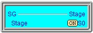
Status Display:
The Status display of the Stage instruction will indicate the ON/OFF condition of the Stage bit, and if ON, the entire box will be highlighted.
See also:
Stage Instructions in the Do-more Controller
SG - Stage
Related Topics:
Stage Programming Concepts
Example 1 - A Simple 2-State Process
Stage Transition Instructions
Example 2 - A Lamp On/Off Controller
Example 3 - A Garage Door Opener
Review - Steps to Writing Successful Stage Programs
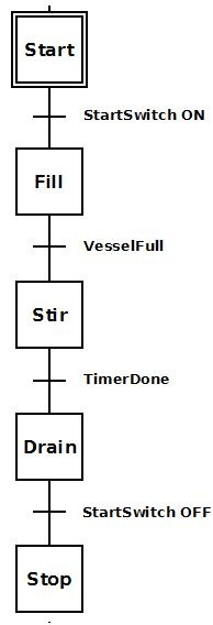 To the right is a stage diagram of a simple sequence
control that would fill a vessel, stir its contents and then drain. It
is good to imagine the sequence before actually writing the ladder logic.
To the right is a stage diagram of a simple sequence
control that would fill a vessel, stir its contents and then drain. It
is good to imagine the sequence before actually writing the ladder logic. To the right is a ladder logic equivalent to the
above stage diagram.
To the right is a ladder logic equivalent to the
above stage diagram.