Topic: DMD0263
Controller LEDs
Do-more controllers in the DL205 series have two-color LEDs that are used to visually provide operational status to the user.
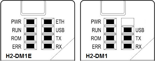
Each of the LEDs can be either RED, GREEN, or YELLOW. The LEDs can be ON continuously or blinking This gives the controller many options for color combinations and blink patterns that can indicate different operational modes, and fault conditions, and provide diagnostic information and communication status.
H2-DM1 and H2-DM1E LED Descriptions
|
PWR |
OFF |
DL205 Base Power of OFF |
|
GREEN |
DL205 Base Power is ON | |
|
YELLOW |
Battery Low - follow this link for information on changing the battery | |
|
|
||
|
RUN |
OFF |
Controller is in STOP (Program) mode |
|
GREEN |
Controller is in RUN mode | |
|
|
||
|
ROM |
OFF |
Non-volatile memory (ROM) is up to date |
|
YELLOW |
Controller is updating non-volatile memory (ROM) | |
|
|
||
|
ERR |
OFF |
Controller is functioning normally |
|
RED |
Controller has experienced a Fatal Hardware Error or a Software Watchdog Error has occurred | |
|
|
||
|
ETH |
GREEN |
Ethernet Link Good |
|
YELLOW |
Ethernet Activity | |
|
|
||
|
USB |
GREEN |
USB is receiving data |
|
YELLOW |
USB is transmitting data | |
|
|
||
|
TX |
GREEN |
Serial port is transmitting data |
|
|
||
|
RX |
GREEN |
Serial port is receiving data |
H2-DM1E LED Pattern Descriptions
In addition to the individual definition of each LED, there are times when the controllers will use combinations of LED ON/OFF state and colors to convey status information. The following combinations use some or all of the LEDs:
ERR LED is blinking RED for (15 seconds) Do-more Designer can blink the ERR led for 15 seconds to verify that a communication link is targeting the correct controller
All eight (8) of the LEDs are ON and the color of each LED is YELLOW indicates the boot loader has started running
All eight (8) of the LEDs are ON and the color of each LED is GREEN indicates the operating system has started running
All eight (8) of the LEDs are cycling through RED & GREEN, in a circular 'chase' pattern indicates the operating system is initializing
The left-most four (4) LEDs are cycling through RED & GREEN, in a 'bouncing ball' pattern indicates the controller is running only the boot loader and is NOT going to load and run the operating system. The most likely cause is having DIP switch #1 in the ON position.
All eight (8) of the LEDs are ON and the color of each LED is RED indicates the hardware watchdog timer has expired because the controller's operating system has stopped running.
See Also:
LED Definitions