Topic: DMD0266
Onboard DIP Switches
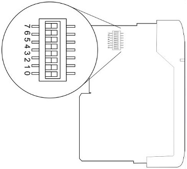
Do-more controller's circuit board has a block of DIP switches that are used to perform various debug and reset operations. The DIP switch settings are only read when the system is first powered up. Changing the settings of the DIP switches requires that the base containing the controller be powered down and the controller removed from the base. The DIP switches can then be changed as required. The controller can then be reinstalled in the base and the system powered back up. The DIP switch block is located on front of the controller's PWB, and is only accessible when the controller is NOT installed in the base.
Description for Individual DIP Switches
0 - ON = Load the oldest copy of the operating system
1 - ON = Stay in the Boot Loader, Do not load the operating system
2 - ON = Disable the hardware watchdog timer - the hardware watchdog is always enabled, but this switch allows the user to override the ability of the Force Watchdog Error (WATCHDOG and Debug Mode to generate a Watchdog condition.
3 - ON = Disable ability to update the firmware and/or gate array
4 - Reserved
5 - Reserved
6 - Reserved
7 - Reset the TCP/IP Network Settings to factory default values - Must be used with DIP #1
DIP Switch / Mode Switch Combinations
Do-more controllers make use of combinations of DIP switch settings and the Mode switch on the front of the controller to perform two reset functions. These reset functions can only be performed when the controller is in the boot loader.
The following sequence describes the steps necessary to perform one of the reset operations. This combination of DIP switch settings and mode switch manipulation is purposely complex to prevent these reset operations from being accidentally executed.
Clear only the Network Settings
This reset function will clear ONLY the Network settings, which consists of the Module ID, Module Name, Module Description, IP Address, Subnet Mask and Gateway Address.
Begin by powering down the controller.
Remove the controller from the base and record the location of the DIP switches (so they can be set back to their original position after the manual reset is finished).
Next set ONLY DIP #1 and #7 ON to perform the Clear Only the Network Settings operation, make sure all other DIP switches are OFF
Reinstall the controller in the base.
Set the controller mode switch to TERM (the center location).
Power up the controller.
At this point the left bank of 4 LEDs should be blinking the 'stay in the boot loader sequence', that is, they should be blinking in sequence, from top to bottom then back to the top, alternating between red and green.
Move the controller mode switch to RUN (to the left)
Move the controller mode switch to TERM (to the center)
Move the controller mode switch to RUN (to the left)
Move the controller mode switch to TERM (to the center)
Move the controller mode switch to STOP (to the right)
Move the controller mode switch to TERM (to
the center) - the LEFT bank of
4 LEDs should now be ON
Note: if you want to terminate the
reset at this point you can do so by moving switch to RUN instead of STOP
or powering down the controller.
Move the controller mode switch to STOP (to the right) - the RIGHT bank of 4 LEDs should now be ON
Note: if you want to terminate the manual reset at this point you can only do so by powering down the controller.
Move the controller mode switch to TERM (to the center) - left bank LEDs begin flashing the power up sequence, and the ROM led should briefly be ON indicating that the data in the ROM is being rewritten. The LEDs will then begin flashing the 'staying in boot loader' sequence indicating the reset is complete.
Power down the controller.
Remove the controller from the base and return the DIP switches to their original positions.
Set the controller mode switch to TERM (in the center location).
Clear All
This reset function will clear everything from the controller, this includes the Network as described above, and the System Configuration, Memory Configuration, all control logic, all Documentation, and all of the User Accounts and Passwords.
Begin by powering down the controller.
Remove the controller from the base and record the location of the DIP switches (so they can be set back to their original position after the manual reset is finished).
Next set all eight of the DIP switches ON to perform the Clear All operation
Reinstall the controller in the base.
Set the controller mode switch to TERM (the center location).
Power up the controller.
At this point the left bank of 4 LEDs should be blinking the 'stay in the boot loader sequence', that is, they should be blinking in sequence, from top to bottom then back to the top, alternating between red and green.
Move the controller mode switch to RUN (to the left)
Move the controller mode switch to TERM (to the center)
Move the controller mode switch to RUN (to the left)
Move the controller mode switch to TERM (to the center)
Move the controller mode switch to STOP (to the right)
Move the controller mode switch to TERM (to
the center) - the LEFT bank of
4 LEDs should now be ON
Note: if you want to terminate the
reset at this point you can do so by moving switch to RUN instead of STOP
or powering down the controller.
Move the controller mode switch to STOP (to the right) - the RIGHT bank of 4 LEDs should now be ON
Note: if you want to terminate the manual reset at this point you can only do so by powering down the controller.
Move the controller mode switch to TERM (to the center) - left bank LEDs begin flashing the power up sequence, and the ROM led should briefly be ON indicating that the data in the ROM is being rewritten. The LEDs will then begin flashing the 'staying in boot loader' sequence indicating the reset is complete.
Power down the controller.
Remove the controller from the base and return the DIP switches to their original positions.
Set the controller mode switch to TERM (in the center location).
See Also:
DIP Switch Definitions