Topic: DMD0255
System Information
The System Information utility provides tabbed views of the runtime status of the Do-more controller, messages generated by the controller, and system events that are logged by the controller. The System Information utility is invoked by selecting the PLC-> System Information menu selection, or clicking the Info button on the Online toolbar.
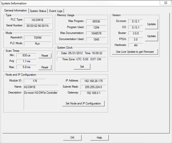
General Information
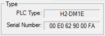 Type - displays the type of controller hardware
and identification
Type - displays the type of controller hardware
and identification
PLC Type - displays the type of controller hardware
H2-DM1 - DL205 series Do-more controller
H2-DM1E - DL205 series Do-more controller with onboard Ethernet
DM-SIM - Do-more Simulator
Serial Number
- the 12 digit serial number of the controller
Do-more controllers without onboard Ethernet - this is a serialized number
Do-more controllers with onboard Ethernet - this is the MAC address of the Ethernet port
DM-SIM - this is the MAC address of the Ethernet adapter in the PC running the Do-more Simulator
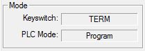 Mode - displays the current PLC mode information
Keyswitch
- the current position of the front panel keyswitch
RUN - the keyswitch is in the RUN position
TERM - the keyswitch is in the TERM position
STOP - the keyswitch is in the STOP position
PLC Mode
- displays the current PLC mode
Program - the controller is not running the project
 Scan
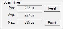
Times - displays the controller's current scan time information
Scan
Times - displays the controller's current scan time information
Min - the shortest scan time since the last PGM-to-RUN mode change
Avg - the average of all the scan times since the last PGM-to-RUN mode change
Min - the longest scan time since the last PGM-to-RUN mode change
Note: click the Reset buttons to clear the Min and/or Max scan time
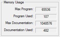 Memory
Usage - displays how much of the controller's program storage is
being utilized
Memory
Usage - displays how much of the controller's program storage is
being utilized
Max Program - the maximum amount of storage in the controller for ladder logic
Program Used - the amount of program storage utilized by the currently loaded project
Max Documentation - the maximum amount of storage in the controller for rung comments and element documentation
Documentation Used - the amount of documentation storage utilized by the currently loaded project
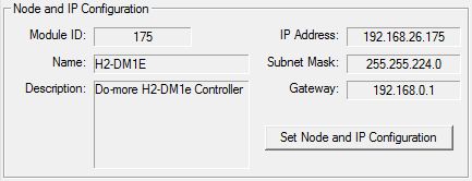 Node
and IP Configuration - displays the current Node configuration
and the setup of the onboard Ethernet port (on models that have them).
These values are initially configured by the NetEdit utility.
Node
and IP Configuration - displays the current Node configuration
and the setup of the onboard Ethernet port (on models that have them).
These values are initially configured by the NetEdit utility.
The values of the fields are also stored in variable memory in the controller as follows: $IPAddress (DST18), $NetMask (DST19), $Gateway (DST20).
 Click the Set Node
and IP Configuration button to open a dialog that will allow the
programmer to change these entries.
Click the Set Node
and IP Configuration button to open a dialog that will allow the
programmer to change these entries.
Note: this is a convenient way to change the TCP/IP configuration of a controller through the USB or Serial port. This allows the programmer access to the TCP/IP configuration of a controller that is not configured to be part of the local network.
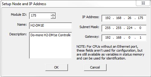
Module ID - set the ID to any positive constant number
Name - set the name to any 255 character combination of alphanumeric and punctuation characters.
Description - set the description to any 255 character combination of alphanumeric and punctuation characters.
IP Address - set the TCP/IP address of the onboard Ethernet port
Subnet Mask - set the Subnet mask for the TCP/IP address of the onboard Ethernet port
Gateway - set the TCP/IP address of the Network Gateway
Note: For controller models that do not have an onboard Ethernet port theses fields are not used for configuration purposes. But, the data in these fields can still be accessed as variables in status memory- $IPAddress (DST18), $NetMask (DST19), $Gateway (DST20) - and used for identification.
Setting the Date, Time, and Time zone
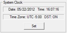 System Clock - displays the current date,
time, and time zone in the controller.
System Clock - displays the current date,
time, and time zone in the controller.
Do-more controllers store the date and time internally in UTC (Coordinated Universal Time), and adjusts for the local time by applying a time zone adjustment specified in minutes.
The Time Zone can be adjusted at runtime by changing the system variable $TimeZone (DST384). Be aware that the time zone is specified in minutes relative to UTC. For example, US Eastern Time is UTC -300 minutes, so $TimeZone (DST384) would contain the value of -300.
Do-more controllers can further adjust for Daylight Savings Time, but this adjustment is done manually to avoid conflict with widely varying local laws.
Daylight Savings Time can be adjusted at runtime through the system variable $SummerTime (ST768). Setting $SummerTime (ST768) to 'true' automatically adds one hour to the local time.
A full discussion of how the Date and Time are handled can be found in the help topic Managing Time in a Do-more controller.
 Click the Set
button to invoke the Set PLC Clock dialog with the following options:
Click the Set
button to invoke the Set PLC Clock dialog with the following options:
Clock Settings
- change the System Clock
Set to PC's
current time settings ... - displays the current date, time, and
time zone settings from the PC running the Do-more
Designer programming software.
Set to manual
settings ... - manually enter the date, time and time zone settings
Date - clicking the down arrow will display a calendar from which you can select the date
Time - clicking the up and down arrows will change the time
Time zone - enter the number of minutes relative to UTC
Daylight Savings Time - click the checkbox to automatically add one hour to the local time
Read PLC Settings - click this button to read the current date, time, and time zone settings from the controller.
Click the Set PLC Clock and Exit button to update the date, time, and time zone settings, then close the dialog
Click the Cancel button to close the dialog and leave the date, time, and time zone settings intact.
 Updating the Controller Firmware
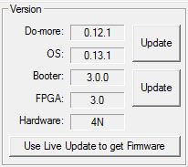
Version
- displays the current version of the firmware in the Do-more
controller, and provides a facility to download the latest firmware and
update the controller.
Do-more - the current version of the instruction set in the controller
OS - the current version of the operation system in the controller
Booter - the current version of boot loader in the controller
FPGA - the current version of the Gate Array code in the controller
Hardware - the current revision of the controller hardware
 Note: LiveUpdate requires a functional Internet connection
to work, make sure the Internet connection is active before running LiveUpdate.
Note: LiveUpdate requires a functional Internet connection
to work, make sure the Internet connection is active before running LiveUpdate.
Click the Use LiveUpdate to get Firmware button to open the Live Update dialog. Live Update will utilize the internet connection to check for new firmware files for the controller, then download it to the Images folder.
Click the Go! button to check for updated firmware files.
Click the OK button to close the LiveUpdate dialog.
Note: updating the controller's operating system will clear all of the controller memory - including the ladder programs and memory contents. If you need to save your project and memory contents first, click the Cancel button and do that work before continuing the update process.
Note: DIP switch #3 is used to Enable/Disable the ability to update the firmware in the controller. This DIP switch must be OFF to allow Do-more Designer to update the operating system or the gate array. Follow this link for more information on the controller's DIP switches.
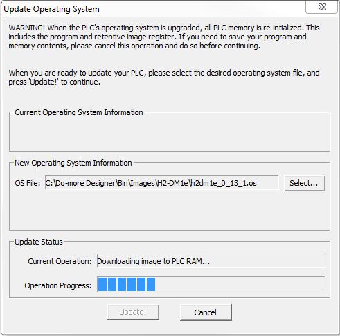 Click the Update
button for the Do-more / OS to invoke the Update
Operating System dialog.
Click the Update
button for the Do-more / OS to invoke the Update
Operating System dialog.
Select... - invokes a File Open dialog to select the operating system file to update the controller. Operating System files generally have the following form: "DM-<major>_<minor>_<build>.os" Browse to the file folder that contains the new firmware file and select the firmware file to use.
Click the Update! button to begin the update progress.
Click the Cancel button to exit without updating the operating system.
Note: There is no fail-safe for the Gate Array and Loader update, which means, if the update process begins and then fails , ** DO NOT TURN OFF THE POWER**, keep trying the update process until it is successful. If you turn off the power without a successful update the controller must be sent back to the factory for repair.
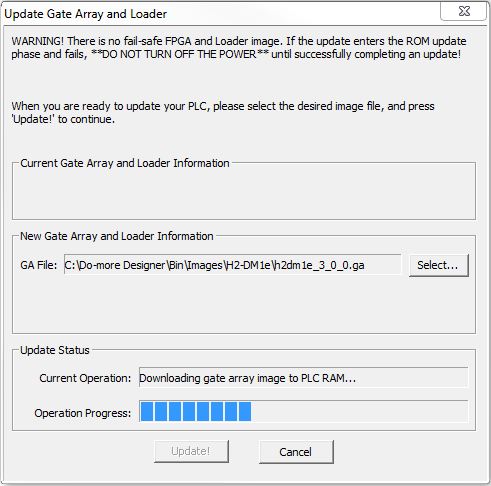 Click the Update button
for the Booter / FPGA to invoke the Update
Gate Array and Loader dialog.
Click the Update button
for the Booter / FPGA to invoke the Update
Gate Array and Loader dialog.
Select... - opens a browser to select the Gate Array and Loader file to update the controller. Gate Array and Loader files generally have the following form: "DM-<major>_<minor>_<build>.ga"
Click the Update! button to begin the update progress.
Click the Cancel button to exit without updating the Gate Array and Loader.
See Also:
General information