Topic: DMD0175
ONDTMR - On Delay Timer
The On Delay Timer (ONDTMR) has one ladder logic input leg which enables and resets the Timer. This Timer "delays turning on", that is, once the input logic turns ON, the Timer will delay turning ON the specified Output by the Timer's On Delay Time value.
If the input logic is ON, the Timer will begin timing, when the input logic is OFF, the Timer will reset, the Timer's accumulator value will return to 0, and the Output will go OFF.
If the input logic goes OFF before the Timer preset is reached the output will remain OFF.

On Delay Timer timing diagram:

Parameters:
Note: Use the F9 key (Element Browser) or Down-Arrow key (Auto-Complete) at any time to see a complete list of the memory locations that are valid in the current field of the instruction.
Timer Struct - specifies a unique Timer structure that will be used by this instruction.
On Delay Time - is the amount of time after which you want the specified Output to go ON. The On Delay Timer has a resolution of 1 millisecond. The maximum value for a Timer Preset is 2,147,483,647 milliseconds. The On Delay Time value can be specified in one of two ways:
Constant - specified using the Time format (HH : MM : SS : mmm).
The maximum Time value in this form is 569
hours, 31 minutes, 23 seconds, and 647 milliseconds. If needed, the value
entered for the On Delay Time will be normalized to it's standard value.
For example, if you entered a value of
When editing the Constant Preset value, the following keystrokes are available
to make entering the value easier and faster:
h - takes you to the Hours field
m - takes you to the Minutes field
s - takes you to the Seconds field
mm - takes you to the Milliseconds field
![]()
Variable - designates a location that contains the total number of milliseconds desired for the On Delay Time. This can be any readable numeric location.
Output - designates a bit location that will be turned ON after the On Delay Time has expired. This can be any writable bit location.
![]()
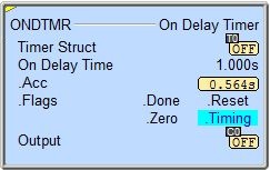
Status Display:
The yellow triangle in the upper left corner indicates this is a Multi-Scan instruction.
The On Delay Timer instruction provides several status values that can be used elsewhere in your ladder program. Their values are updated each time the ONDTMR instruction is processed. The syntax for using them is <timer struct>.<flag name>, for example, T7.Acc.
- .Acc (Accumulator)
- a 32-bit signed value that represents the total elapsed time since the
On Delay Timer was enabled
- .Done - is ON any
time the On Delay Timer is enabled an it's accumulator value (.Acc) is
greater than or equal to the On Delay Time value
- .Reset - is ON
if the input logic is OFF, or if the Timer is being reset by an RSTT instruction
- .Zero - is ON any
time the On Delay Timer's accumulator value (.Acc) is 0
- .Timing - is ON if the On Delay Timer is enabled
See Also:
ONDTMR - On Delay Timer
Rung Example:
