Topic: DMD0023
FREQTMR - Frequency Timer
The Frequency Timer (FREQTMR) instruction is used to convert the rate of a series of pulses to engineering units by measuring the time between the leading edges of successive pulses, normalizing that value to the desired time base, then scaling that value to the desired engineering units. This type of scaling is typically done for speed, flow rate, velocity, etc..
This instruction operates in a similar manner to the Interval Scaling operation in the CTRIO modules.
The Frequency Timer is always enabled, but the timeout period only begins after receiving the first input pulse. If a Timeout occurs, or the Reset is asserted, the timeout period again starts after an input pulse is received.
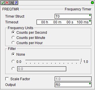
Parameters:
Note: Use the F9 key (Element Browser) or Down-Arrow key (Auto-Complete) at any time to see a complete list of memory locations that are valid in the current field of the instruction.
Timer Struct -
Timeout - specifies the maximum
amount of time to wait between input pulses. If the Timeout value is reached,
the current calculation is cancelled and the output value is set to 0.
The Timeout is specified using the Time format
(HH : MM : SS : mmm). The maximum Timeout
value in this form is 569 hours, 31 minutes, 23 seconds, and 647 milliseconds.
If needed, the value entered for the Timeout will be normalized to its
standard value. For example, if you entered a value of 97 Seconds, that
value will be converted and displayed as 1 Minute and 37 Seconds.
When editing the Timeout value, the following keystrokes are available
to make entering the value easier and faster:
h - takes you to the Hours field
m - takes you to the Minutes field
s - takes you to the Seconds field
mm - takes you to the Milliseconds field
Frequency Units - specifies
the output scaling factor
Counts per Second - scales the input pulse count to Counts per Second
Counts per Minute - scales the input pulse count to Counts per Minute
Counts per Hour - scales the input pulse count to Counts per Hour
Filter - enables a filtering
algorithm that is applied during the calculation that defines how much
'weight' the current-value is given versus the latest-calculated-value.
Filtering acts as a data smoothing function, balancing stability versus
the responsiveness of the calculated value as it responds to changes in
the input pulse rate. A large filter value gives more weight to the latest-calculated-value
(and hence less weight to the current-value), producing a more stable
value that responds more slowly to changes in the input pulse rate.
None - the filtering algorithm is disabled
0.0 - 1.0 : Sliding Scale - sliding the slider to the right increases the filter constant. Note: the scale is a logarithmic (non-liner) scale, the mid point of the filter value is about 1/3 of the scale.
0.0 : Constant Value - This can be any constant floating point value between 0.0 and 0.999999.
Scale Factor - optionally applies a scaling factor to the calculated value, for example, to convert counts per second to engineering units like gallons per seconds.
Output - designates a location to store the scaled output value. This can be any writable REAL location.
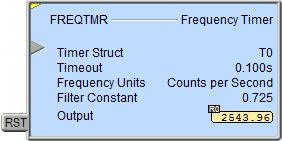
Status Display:
The yellow triangle in the upper left corner indicates this is a Multi-Scan instruction.
The first input leg is the Pulse Input. The gray triangle at the right
end of an input leg indicates the input is edge
triggered
The second input leg is the Reset (RST). When this input logic is ON, the Frequency Timer's output value will be set to 0.0.
See Also:
FREQTMR - Frequency Timer
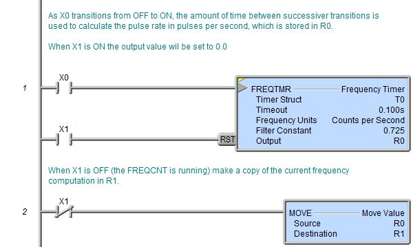
Rung Example: