Topic: DMD0067
DRUM - Drum
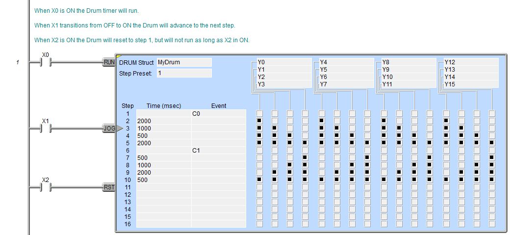
The Drum (DRUM) instruction is used to mimic the operation of a mechanical Drum (sometimes called a drum sequencer). Drum instructions are well suited for repetitive processes that consist of a finite number of steps. As such, they can do the work of many rungs of ladder logic with elegant simplicity.
Important Note: The outputs specified in the Drum instruction are enabled any time the Do-more controller is in Run Mode - the Start input does not have to be ON, and the Reset input does not disable the outputs. Upon the Do-more controller entering Run Mode, the Drum instruction's outputs automatically turn ON or OFF according to the pattern of the preset step. This includes any effect of the optional Output Mask.
Drum instruction parameters are best described by examining the mechanical drum after which the Drum instruction is modeled. The mechanical drum is typically a cylinder with pegs on its curved surface. The pegs are populated in a particular pattern which represents a set of desired actions for machine control. A motor or solenoid rotates the drum a precise amount at specific times. During this rotation, stationary wipers sense the presence of pegs (present = ON, absent = OFF). This design makes or breaks electrical contact with the wipers, creating electrical outputs from the drum. The outputs are wired to devices on a machine for On/Off control. The contact closure of each wiper generates a unique on/off pattern called a sequence. Because the drum is circular, it automatically repeats the sequence once per rotation.
Drums have a finite number of positions within one rotation; these are called Steps.
At power-up or any time the Drum's RST input (3rd input leg) is ON the Drum is reset to a predetermined step called the Step Preset.
The drum rotates from one step to the next based on its internal timer, or some external event, or a combination of the timer and the external event.
If needed, a machine operator can manually increment the drum step using a Jog control (2nd input leg) on the drum's drive mechanism.
In Do-more Designer the mechanical drum is represented in chart form. Imagine slicing the surface of a hollow drum cylinder between two rows of pegs, then pressing it flat. The drum can now be viewed as a chart. Each row of the chart represents a Step, numbered 1 through 16. Each column represents an output, numbered 0 through 15 (to match word bit numbering). The grid of empty squares on the right represents the surface of the drum where the pegs would be placed. Clicking on a square fills in that square, and this represents the ON state. On the mechanical drum this would be a peg, and the open squares would represent empty peg sites.
Parameters:
Note: Use the F9 key (Element Browser) or Down-Arrow key (Auto-Complete) at any time to see a complete list of the memory locations that are valid in the current field of the instruction.
DRUM Struct -- designates a
name to uniquely identify the Drum. This can be a either a new heap item
Note: If you choose to create a new heap item, be aware that this will change the System Configuration, and changes to the System Configuration can only be saved to the controller in PROGRAM mode. Run mode updates can not be performed until these System Configuration changes have been saved to the controller. For more information on heap items and pre-allocating one or more Drums refer to the Memory Configuration section in the System Configuration utility.
If the DRUM Struct field is changed for any reason, the dialog at the right will be displayed.
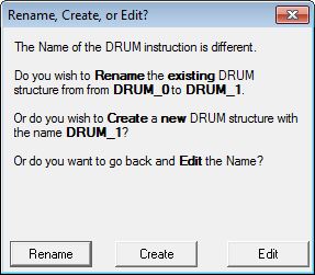
Rename - choosing this option will rename the existing DRUM Struct. This will cause a change to the System Configuration which can only be saved to the controller in PROGRAM mode. One situation where this would occur is after a copy/paste operation of an existing DRUM Struct and the reference of the newly pasted DRUM must be changed.
Create - choosing this option will create a new heap item, and the existing DRUM Struct will not be affected. This will cause a change to the System Configuration which can only be saved to the controller in PROGRAM mode. One situation where this would occur is after a copy/paste operation of an existing DRUM Struct and the reference of the newly pasted DRUM must be changed.
Edit - choosing this option will return to the Drum Editor
Step Preset - designates which Step in the Drum to start executing when the Drum is first enabled, and whenever the DRUM is Reset. This can be any value between 1 and 16 or any readable numeric location. If an invalid Step number is entered the Status Bit $OutOfRange (ST132) will be ON and an error message will be generated. The Step Preset is typically the constant value 1, but one situation where i makes sense to use a variable location is when the Drum initially needs to start at Step 1, but on subsequent passes it needs to start at a later Step, skipping over some 'homing' steps.
Adding Steps to a Drum
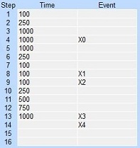
Each Step in a Drum is a row that consists of a dwell Time for that step, and/or a terminating Event for that step, and an ON/OFF designation for each of the outputs in the Drum.
A Step does NOT require both a Time and an Event, a step can have either a Time or an Event or both. Note: if both a Time and an Event are entered for a Step, the dwell Time will run only when the Event is true.
Drum (DRUM) instructions do NOT require that all of the Steps be utilized, Note: if neither a Time or an Event are entered for a Step that Step will be skipped.
Once the Drum has executed the last Step, the outputs remain in the
pattern defined for the last Step.
Time Only - specify the amount
of time (in milliseconds) to dwell on the current step. This can be any
positive integer between 0 and 2147483647 or any readable numeric location.
When the drum enters a Step, it sets the output pattern indicated then
it begins timing down from the specified Time value. When the Time has
expired the Drum moves to the next Step.
Event Only - when the drum enters
a Step, it sets the output pattern indicated then it begins polling the
discrete input programmed for that step. As soon as the Input is ON the
Drum transitions to the next Step.
Timed Event - the time field specifies the amount of time (in milliseconds) to dwell when the element specified in the Event field is ON. The Step will not time when the Event field element is OFF. This can be any positive integer between 0 and 2147483647 or any readable numeric location. When the drum enters a Step, it sets the output pattern indicated then it begins timing down from the specified Time value. When the Time has expired the Drum moves to the next Step.
The Output Control Grid uses
rows and columns of squares to mimic the pegs and gaps of the mechanical
drum. A square that is empty represents a gap (or missing peg, or OFF
state).
Clicking on the square with the mouse (or the space bar on the keyboard)
will fill in the square, which represents a peg (or ON state).
Clicking on a square that has already been filled in will empty that square.
Clicking and dragging the mouse cursor over a group of squares will select
multiple rows and columns and will fill in all of the selected squares.

Selecting Drum Outputs
The Output section contains
4 groups of 4 entries, for a total of 16 possible outputs. These Output
entries can be any
Each Output is 'connected' to a column in the Output Control Grid and turned ON an OFF by the state for each Step as the Drum moves through each of the Steps defined in the Output Control Grid.
Drum (DRUM) instructions do NOT require that all of the Output entries be used.

Using the Optional Drum Output Masks
When Output Masks are used the Drum instruction will only change the Discrete Output if the corresponding bit in the mask is set to 1. If this bit in the mask is 0, the state of the output is not changed by the Drum. Using Output Masks gives other parts of the program the ability to override the control of the discrete outputs that are referenced in the Drum.
![]() Output Mask - designates
the first DWord (32-bit) location of a range of locations that will be
used as Output Masks. Each step in the Drum instruction has its own Output
Mask. The range of Output Mask addresses is displayed between the Output
groups and the first step's Output grid pattern.
Output Mask - designates
the first DWord (32-bit) location of a range of locations that will be
used as Output Masks. Each step in the Drum instruction has its own Output
Mask. The range of Output Mask addresses is displayed between the Output
groups and the first step's Output grid pattern.
The Output Mask address for a specific step is offset from the first address in the range, based on its step number. For example, the Output Mask address for step 1 is the first address in the specified DWord range, the Output Mask for step 7 would be the seventh DWord address in the specified range, etc.
Each Discrete Output in the Drum is labeled 0 through 15. These labels correspond to that specific bit in the step's Output Mask word.
Note: be aware of the bit ordering when entering values for the Output Mask, bit 0 (the mask bit for Output 0) is on the far left, and bit 15 (the mask bit for Output 15) is on the far right, which is backwards from the way traditional Hexadecimal or Decimal values are displayed. The Drum instruction only uses the lower 16 bits of each Output Mask address, upper 16 bits of each Output Mask are reserved for future use. Use bit casting to reference a specific bit in a Step's mask register, for example, D0:0 to reference the first Step's mask for Output 0, or D13:7 to reference the 14th Step's mask for Output 7.
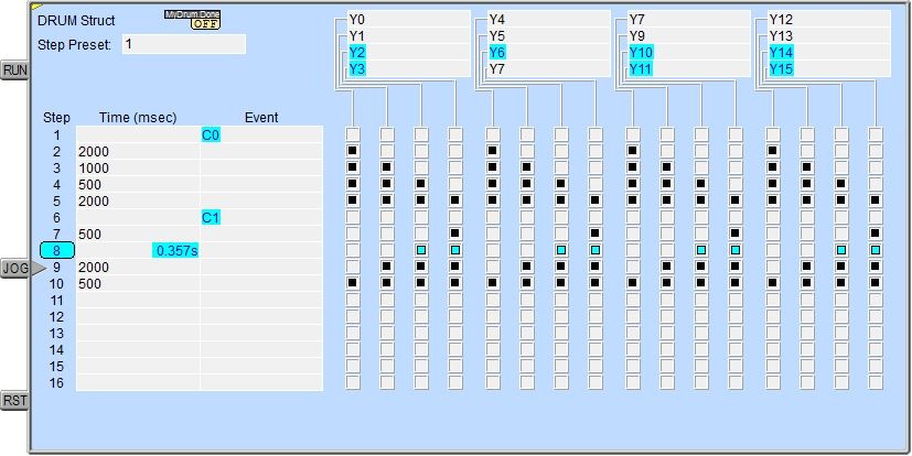
![]() With status enabled, each bit in the Output Mask
that is a 1 will be displayed as a "connector" between the Output
Control Grid and the Outputs; and each bit that is a 0 will be displayed
as a gap.
With status enabled, each bit in the Output Mask
that is a 1 will be displayed as a "connector" between the Output
Control Grid and the Outputs; and each bit that is a 0 will be displayed
as a gap.
Drum Input Legs
The yellow triangle in the upper left corner indicates this is a Multi-Scan instruction.
The first input leg (RUN) is
the Run input. When this input logic is ON the Drum's internal timer is
running. When this input logic is OFF the Drum's internal timer will stop.
Note: When the Run input goes OFF
the internal Timer will stop at the current value and will resume at that
time value when the Run input goes back ON.
The second input leg (JOG)
is the Jog input. The Jog input is edge triggered
The third input leg (RST) is the Reset input. When this input logic is ON the Drum will move to the Preset step and the Drum's internal timer will reset to 0 and will remain in the Reset state as long as this input is ON. Note: The Reset input has priority over the Run and Jog inputs, meaning that if either the Run or Jog inputs are ON at the same time as the Reset input, the Drum will NOT Run and the Jog input will NOT cause the Drum to change the current Step.
Drum Structure Fields
The drum structure contains several "dot" fields that can be used elsewhere in the project. Their values are updated each time the Drum instruction is processed. The syntax for using them is <drum struct>.<flag name>.
The following is a list of the"dot" fields that are programmatically
accessible for each Drum (DRUM) instruction:
.Jog - will be ON when the Jog input is ON, and OFF when the Jog input leg is OFF
.Run - will be ON when the Run input is ON, and OFF when the Run input leg is OFF
.Reset - will be ON when the Reset input is ON, and OFF when the Reset input leg is OFF
.Done - will be ON when the Drum has completed the last step, and OFF when the Drum has not finished the last step
.Step - an unsigned Byte that represents the step number in the Drum that is currently executing
.Mask - a 32-bit unsigned value that has the current Output Mask value - this value is best viewed in Hexadecimal or Binary format
.State - contains a 32-bit word that represents the current Step's ON/OFF state of the 16 outputs BEFORE any mask state is applied. The DWord location will contain a 1 for each output that should be ON and a 0 for each output that should be OFF.
.TimeLeft - contains the amount of execution time remaining for the currently executing Step in the Drum (in milliseconds)
Data View Display Formats
There are 4 variations of the Data View display of a drum structure, each with different amounts of data and/or different display orientations. Note: These formats are for display purposes only, the structure's variables cannot be edited when displayed using any of these display formats.
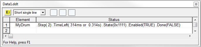
Short Single Line:
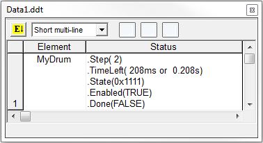
Short Multi-Line (the default):
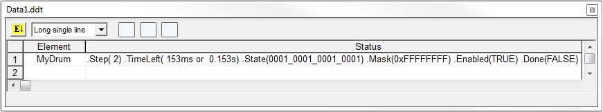
Long Single Line:
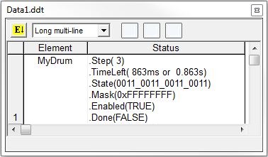
Long Multi-Line:
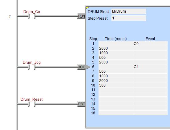
Rung Example: