Topic: DMD0161
SR - Shift Register
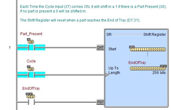
The Shift Register (SR) instruction shifts data through a predefined number of BIT locations. These BIT locations can be a range of BITs, a single Word or DWord, or a range of Words or DWords.
Parameters:
Note: Use the F9 key (Element Browser) or Down-Arrow key (Auto-Complete) at any time to see a complete list of the memory locations that are valid in the current field of the instruction.
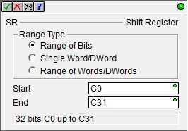
Range Type - designates the
memory locations that will be used by the Shift Register instruction.
Select one of the following three options for the Range Type:
Range of BITs - designates a range of contiguous BIT memory locations. When using this memory type, you must adhere to the following restrictions:
the range must be at least 8 BITs long
the range must be multiples of 8 BITs in length
the maximum range is 2048 BITs
the range must start at beginning of an 8-bt boundary and end at the end of an 8-bit boundary, for example: C0 - C7 is valid, C0 - C10 is not. Ignore any bits at the end if a multiple of 8 bits is not required in the application
the direction the BITs will shift is determined by order of the values you enter, for example: C0 - C15 shifts Up, and C15 - C0 shifts Down
the range can be any writable bit location.
Single Word/DWord - designates a single Word (16 bit) or single DWord (32 bit) location.
the direction the BITs will shift is always Up, for example: if you select D0, the BITs will shift from D0:0 Up to D0:31
this can be any writable Word or DWord numeric location.
Range of Words/DWords - designates a range of contiguous Word or DWord locations.
the maximum number of contiguous Word locations is 128
the maximum number of contiguous DWord locations is 64
the direction the BITs will shift is determined by order of the values you enter, for example: V0 - V3 shifts Up from V0:0 to V3:15, and V3 - V0 shifts Down from V3:15 to V0:0
this can be any writable Word or DWord numeric location.
Start - if Range of Bits or Range of Words/DWords is selected this entry designates the first memory location to use. If Single Word/DWord is selected, this is the single memory location to use. This can be any writable Bit or Word/DWord location.
End - if Range of Bits or Range of Words/DWords is selected this entry designates the last memory location to use. This can be any writable Bit or Word/DWord location.
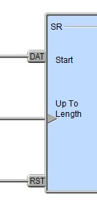
Input Legs:
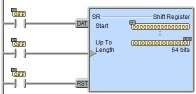
The Shift Register (SR) instruction has the following three ladder logic input legs:
The first ladder logic input leg (DAT) is the Data signal. This determines the value (one or zero) that will enter the shift register.
If the input logic is ON a value of 1 will
be placed in the starting location of the shift register with the next
transition of the Clock signal.
If the input logic is OFF a value of 0 will be placed in the starting location
of the shift register with the next transition of the Clock signal.
The second ladder logic input leg is the Clock signal. The gray triangle
at the right end of an input leg indicates the input is edge triggered
The third ladder logic input (RST) is the Reset signal. When ON, the Reset signal resets all bit positions in the shift register locations to zero.
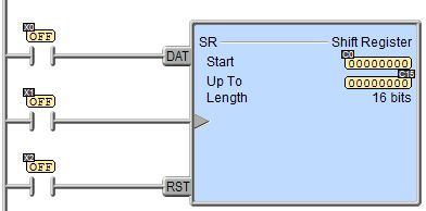
Status Display:
The status display of the Shift Register will display as many of the registers being used as possible. If the full range of the registers cannot be displayed in the instruction, only the first and last registers will be displayed.
This configuration uses bits C0 to C15, status for all 16 bits can be displayed in the instruction.
This configuration uses bits C0 to C63, status for all 64 bits cannot be displayed, only the first 16 bits and the final 16 bits are displayed.
This configuration uses a single DWord D0, status for all 32 bits can be displayed in the instruction.

This configuration uses Words V0 and V1, status for all 32 bits can be displayed in the instruction.

This configuration uses DWords D0 to D9, status for all 320 bits cannot all be displayed, only the first 16 bits of D0 and the final 16 bits of D9 are displayed in the instruction.

See Also:
SR - Shift Register
Example: